Subsections of Logging
ECU Logger
EFI Relay control is very important for stable logging recording, this is due to memory transfer from high speed ram in the ECU to permanent memory when the ECU is shut down.
Overview
ECU logging allows ECU Engine and Vehicle data to be transferred into memory and then permanently stored. When required the data can then be downloaded from the ECU using Emtune so it can be analyzed.
The ECU logging uses 2 types of memory for data storage.
- RAM (Volatile - ECU requires power to maintain the stored data).
- Flash Memory (Non-volatile - Data is permanently stored).
Stage 1
The logging starts by first transferring data into a large high speed DDR RAM buffer. This can store up to 32MB of data. RAM memory is volatile which means when the power is removed the data is lost. It is fast and has an unlimited number of Write(Store) and Read cycles.
Stage 2
As the RAM data can be lost when the ECU is powered down, the data must be periodically transfered into Flash Memory where is can be permanently stored. Flash memory has a limited number of write (Store) cycles which is why the data can only be stored periodically. The following condition(s) are used to control this storing:
- When a logging channel is ON, Data is transferred from RAM into Flash memory at approximately 30sec intervals.
- When a logging channel switches from ON to OFF all unstored data is transferred into Flash memory.
- When the ECU is controlling the Main EFI Relay and the ECU receives a request to shut down, the ECU will transfer all unstored data into Flash Memory before switching itself off.
Logging rates can be selected from 1Hz up to 500Hz.
Data can be transferred from ECU to PC at approximately 0.5MB/sec. So a 4MB log will take 8 seconds and a 16MB log will take 32 seconds.
Tip: Use the Runtime menu (F3) > ECU Internal tab to view the Logging Status
NOTE: With 500 Hz Rate selected ONLY Dataset 1 is available for logging .
Logging Start Conditions
For ECU logging to START for a selected Dataset the following must occur:
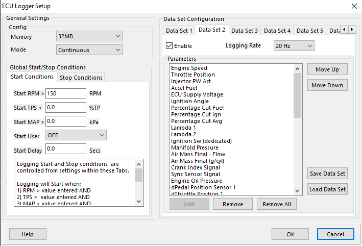
- RPM is greater than RPM Start AND
- TPS is greater than TPS Start AND
- MAP is greater than MAP Start AND
- Selected User Channel is ON (if Enabled) AND
- Logging Switch Status is ON (if Enabled) AND
- Start Delay time has been reached.
Entering a 0 into any of the Start Parameters means it will not be used to control the start of logging.
If ALL Start conditions are zero, the logging will never start.
If ONLY the logging switch is required then assign this to an input using the Inputs Pins Setup menu (F10), switches Tab and then set ALL the Start parameters to zero.
Logging Stop Conditions
For ECU logging to STOP for a selected Dataset the following must occur:
- RPM is less than RPM Stop AND
- TPS is less than TPS Stop AND
- MAP is less than MAP Stop AND
- Selected User Channel is OFF (if Enabled) AND
- Logging Switch Status is OFF (if Enabled) AND
- Stop Delay time has been reached.
Entering a 0 into any of the Stop Parameters means it will not be used to Stop the logging.
If ALL Stop conditions are zero, the logging will never stop. This should be avoided. Make sure the Stop conditions are set correctly.
If ONLY the logging switch is required then assign this to an input using the Inputs Pins Setup menu (F10), switches Tab and then set ALL the Stop parameters to zero.
Calculating Logging Time
Time to 100% fll the ECU logging Memory can be calculated with the following equation:
NOTE: When the logging mode is set to “Circular” this is the time to complete one logging cycle
Example1 :
- Dataset 1 Logging Rate = 100Hz. Logging 20 parameters.
- Memory Size at 4MB
Example2 :
- Dataset 1 Logging Rate = 100Hz. Logging 20 parameters.
- Dataset 2 Logging Rate = 5Hz. Logging 20 parameters.
- Memory Size at 4MB
Example3 :
- Dataset 1 Logging Rate = 100Hz. Logging 50 parameters.
- Memory Size at 32MB
Data Set Configuration
There are 6 data sets that can hold 50 channels each.
Each data set has select-able “Logging Rate” so the user can manage what channels are being recorded at what speeds.
PC Logger
Software Navigation
From the Welcome Screen, you can Open Log directly from there. This will open the software in a limited viewing mode where the logging view is only available.
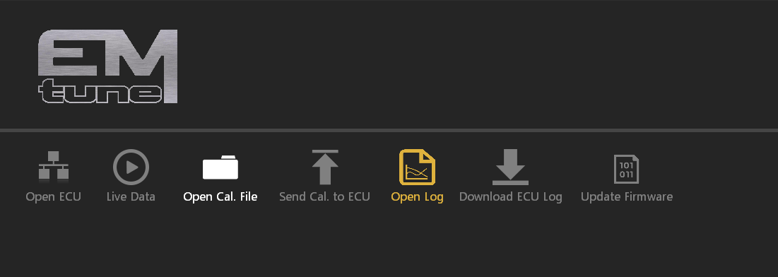
Otherwise, when the ECU, or a calibration file is open, navigating over to the Logging tab at the top will put you into the Logging section.
From here, you can navigate through a number of menus, tabs, sub tabs, etc.
Opening a log file
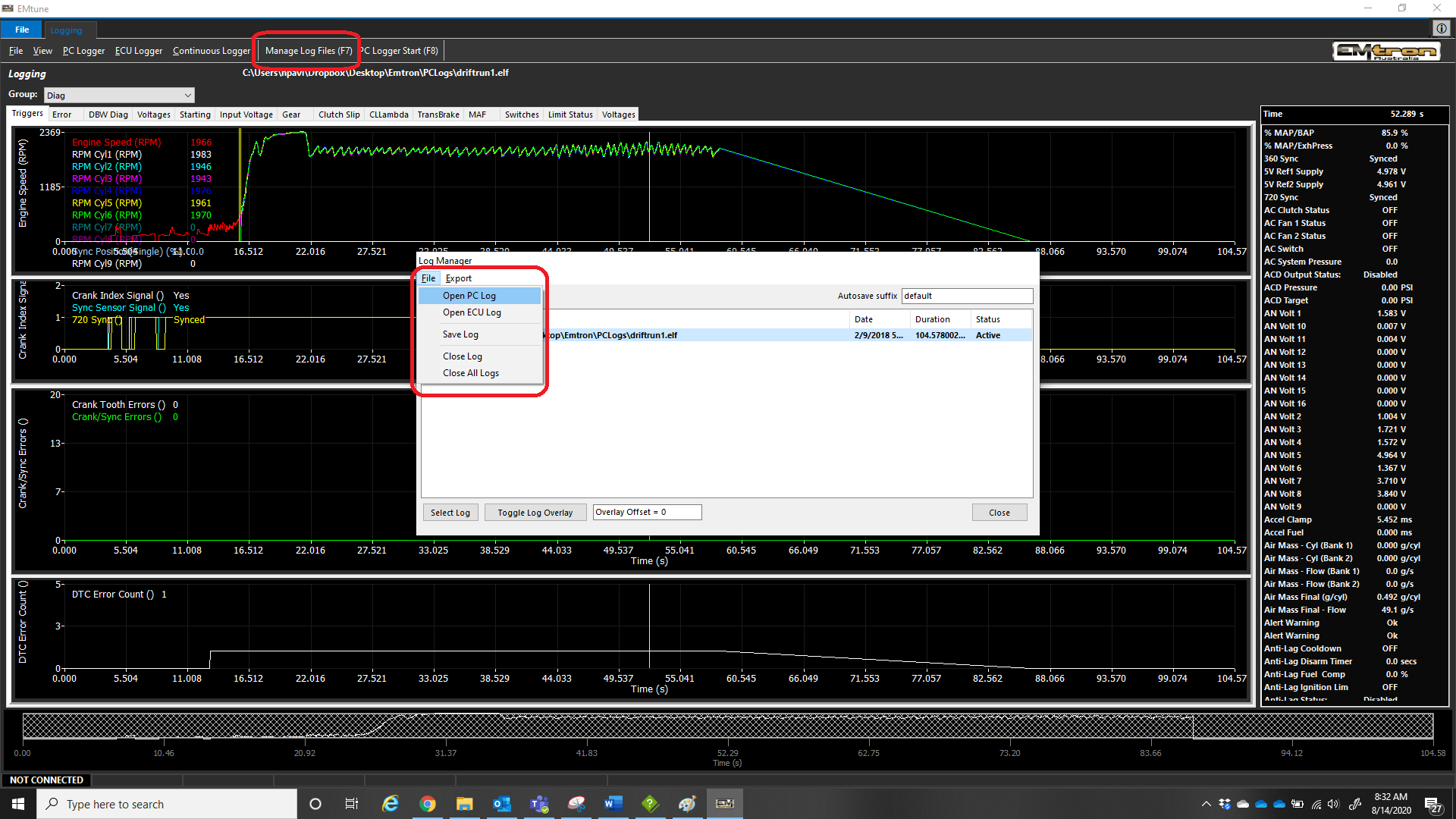
Select “Manage Log Files” or press hotkey (F7)
Use the file menu to open PC/ECU Log file (".elf" files) and they will populate the log manager list so you can easily switch between log files
PC Logging
PC logging allows the ECU to record all channels available with the PC (at medium rates). The PC logger is a very powerful tool for this reason, as it can diagnose many issues. Technical support will almost certainly request a “PC Log” for most inquiries.
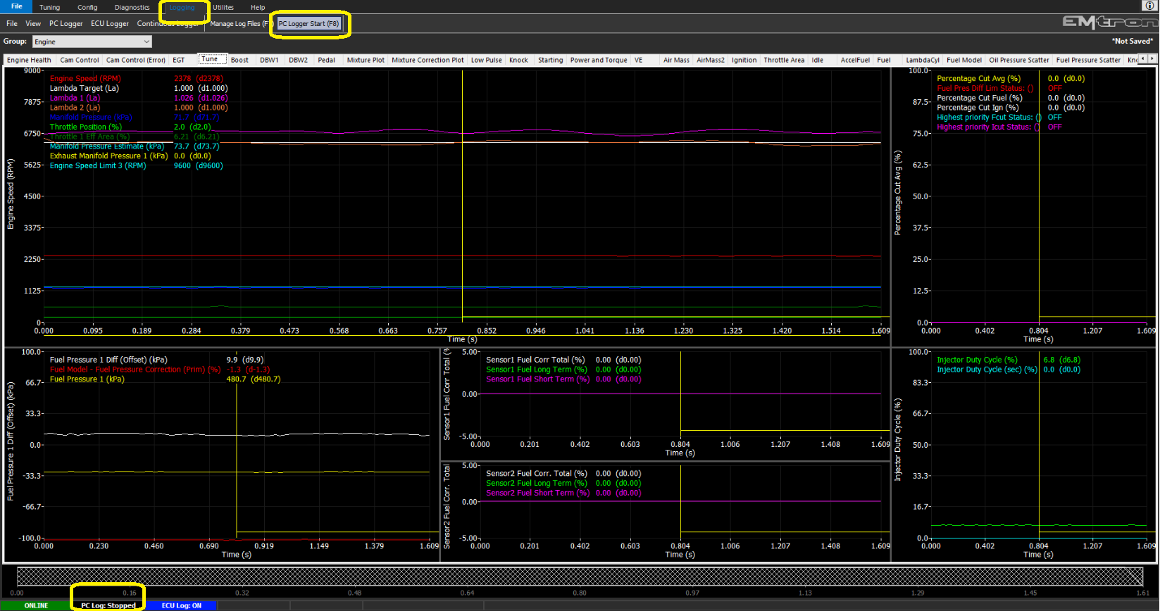
Starting and stopping a PC log is done either in logging tab by clicking “PC Logger Start (F8)”, or just by simply pressing “F8” key on the PC. Logging will confirm recording has begun on the bottom left with a Blue confirmation
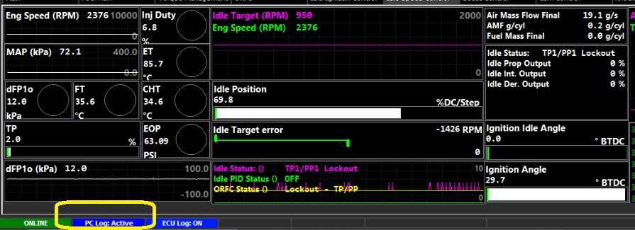
** All PC logs will auto save to your hard drive under the specified paths (File -> Options)
When stopping the PC log, the ECU will direct you into the logging view (can be turned off - set ON by default)
Saving a log file
Select “Manage Log Files” or press hotkey (F7)
Use the file menu to save PC/ECU Log file (".elf" files) and they will populate the log manager list so you can easily switch between log files
** Double click the log file you want to save in a new location
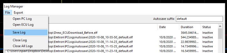
* PC Logs will auto save to your hard drive under the specified paths (File -> Options)
Overlaying a log file
With two or more log files in the log manager, Select the second log file and click “Toggle Log Overlay”
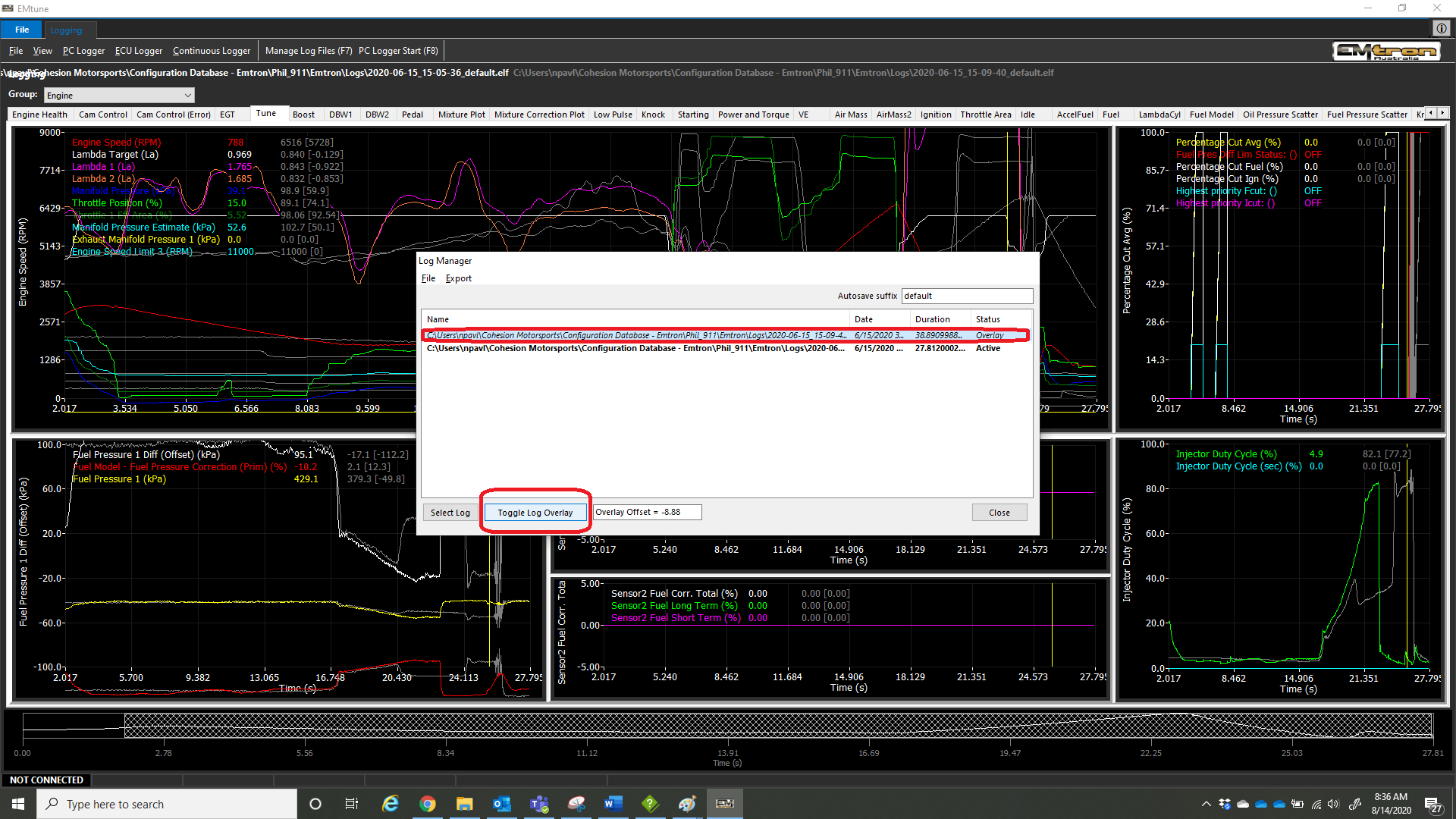
The overlay offset can be entered in, however inside the logger once the Log Manager is closed, hot keys can be used to shift the log view around
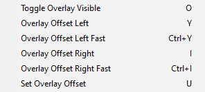
** Right Clicking the logging area will show all hot keys available
Managing groups, pages, and complete layout
Under the “View” tab, all management of the logging layout can be configured. Each logging page can be individually exported and saved, as well as the complete layout
** It is highly recommended that users back up their logging layout periodically
** New Emtune version installations will ask you to overwrite the logging layout
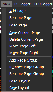
Setting up Graphs
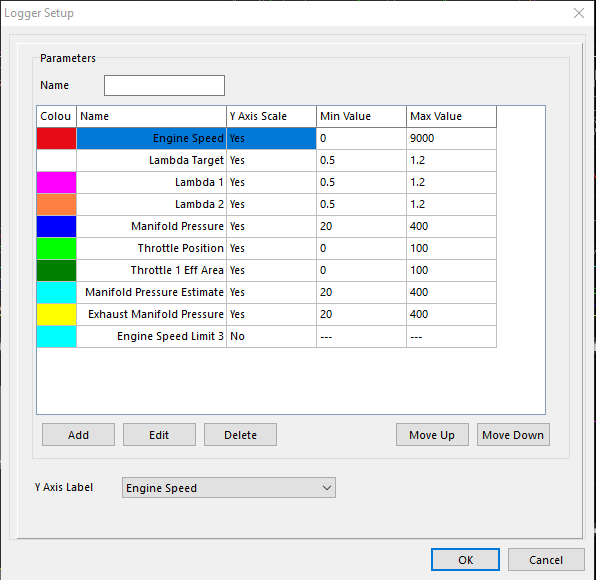
Right clicking in the page, then clicking Setup Graphs brings up the menu choices to choose channels for line graphs.
Choose your channels, min/max scales for each channel, what channel ultimately you want on your Y-Axis label
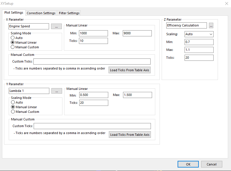
Setting up XY Plot
XY Plots have similar settings. Set up X and Y channels. Z channel will be the color channel for the dot plot to populate.
There are also correction and filter settings that can further customize the XY Plot
** XY Plot Correction is covered in a different section
Calculated Channels
Calculated Channel Setup
Calculated Channels are available for users to set up inside Emtune
** These channels are only available “software side” for use in the logger, live dash channels, and programmable parameter channels (Set Cell to Parameter Value), and cannot be used as permanent ECU channels
Calculated Channel Examples
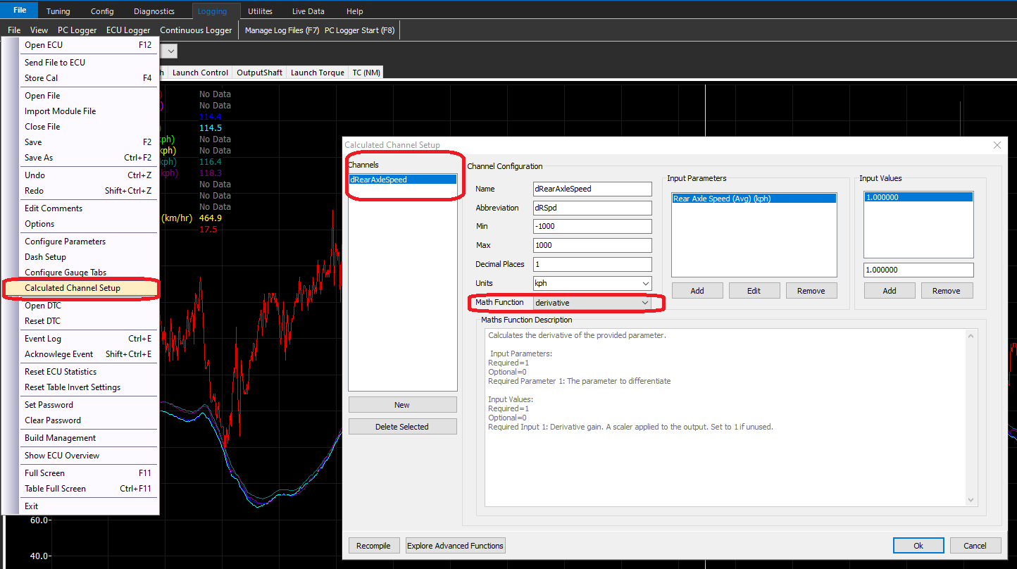
Calculated Channels are accessed via the File Menu.
A “new” channel can be created, where the user can define name, abbreviation, min/max, units, etc.
There are pre-defined Math Functions that can be selected, in which the Maths Function Description will dictate how it can be used.
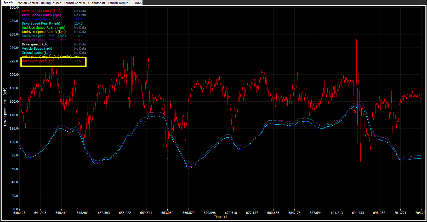
Derivative Speed Example
The example above is showing how the derivative math function can be used to create a channel for the Rear Axle Speed channel.
Once created, the channel can be selected in the logger, live dash, or programmed as a Set Cell Value (Q).
Simple Channel Re-naming
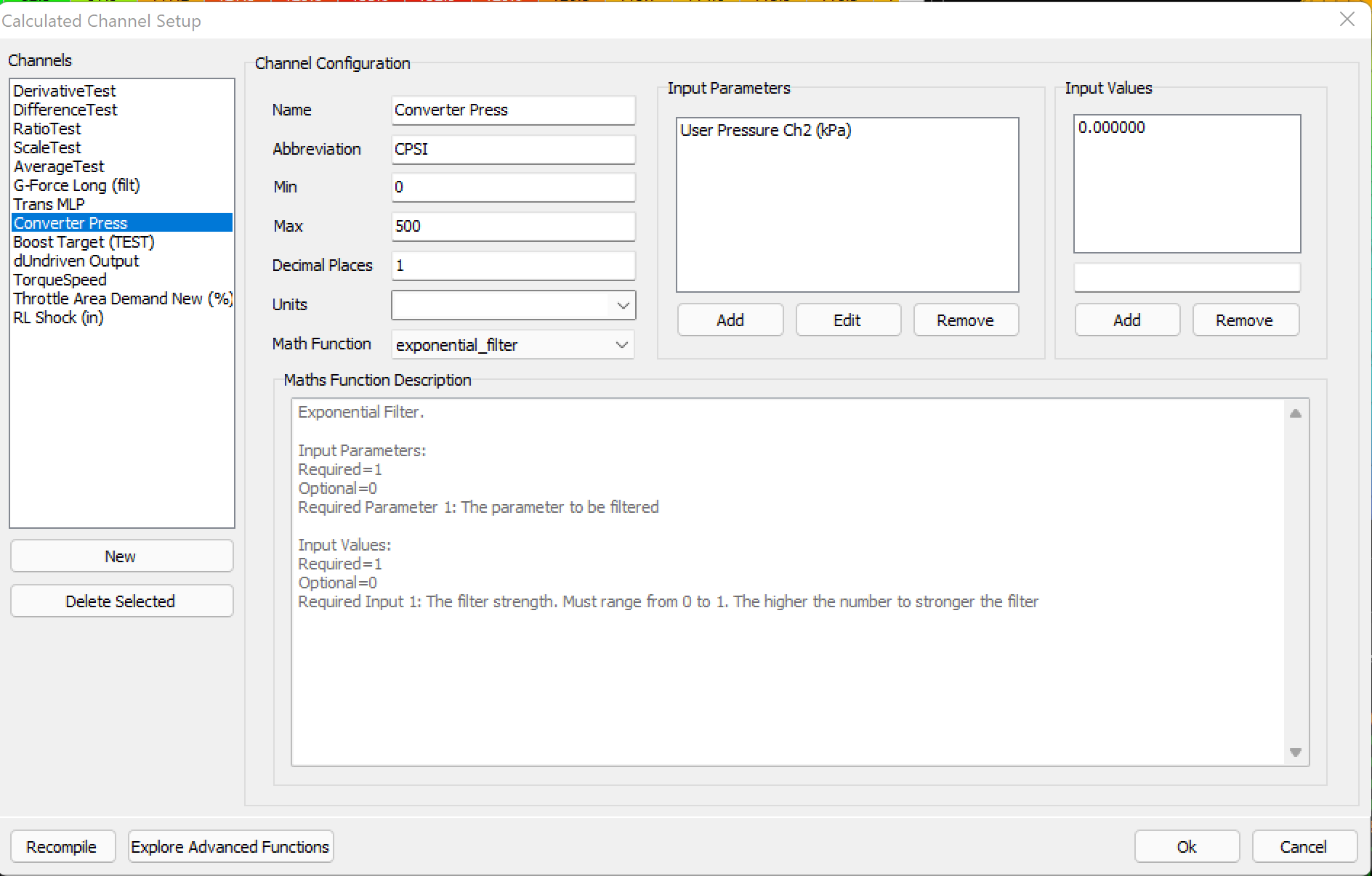
The example above is showing how the User Pressure 2 channel name is being converted to a name that can be easily displayed.
The Exponential Filter math function is being used (a math channel MUST be selected), however the filter strength being set to 0.000 will output a 1:1 value in the logger exactly as the User Pressure 2 channel is being reported
** A different math function can be used, such as “sum”, with no actual sum (0.000).
Channel Re-naming with math
In some cases, channels may need re-naming, but also an offset applied to them. Most commonly if a sensor needs a simple way to “zero” it’s value. Instead of re-scaling the sensor in the sensor input every single time, this can be done in the calculated channels.
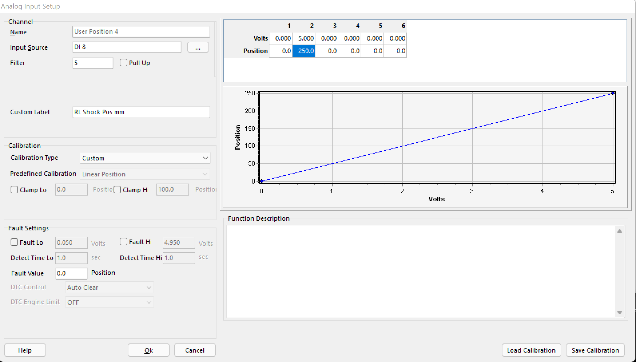
A User Position is set up here for a rear shock sensor.
The voltage range represents it’s complete range (0-250mm)
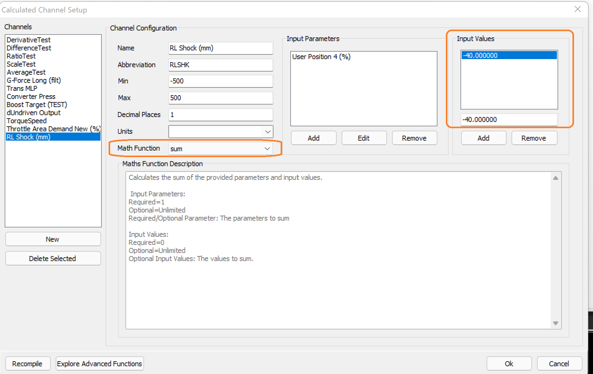
The calculated channel is created using the “sum” Math Function.
The Input variable of -40, zeros the value in the data logger/live parameters.
The value needed can be derived easily by looking at the current User Position channel, and then quickly entered to adjust the value, without re-scaling the position input.
Advanced Functions
Advanced Math Functions can be added by the user themselves.
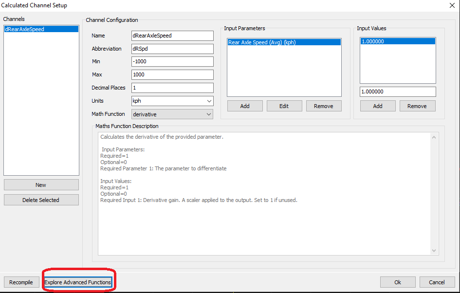
Clicking Explore Advanced Functions allows the user to import new .dll files as new Math Functions
Creating New Functions
To create a new function, firstly - Download the c compiler: https://github.com/llvm/llvm-project/releases/download/llvmorg-10.0.0/LLVM-10.0.0-win32.exe
** When installing, ensure you check the box saying ‘add to path’ or else Emtune will not be able to find the compiler.
To add a new function, you need to create a source file for the function. The file extension must be .c and not contain any spaces.
There is an example file in the source directory for the users to use as a template:
Example: testfunction.c
The new file should look like this (don’t worry too much about the icon):

Open the file in a text editor compatible with .c files such as - Notepad++ https://notepad-plus-plus.org/downloads/
To get started you can paste the following into your new math function as a starting point:
** The file in the source folder called math_function.h contains more technical information about how the math functions work.
This is the source for the derivative function shipped with Emtune.
Once pasted in, at the very least, the function name must be renamed.
Changed the line:
char *name(void) { return “derivative”; }
to
char *name(void) { return “testfunction”; }
This is the name that will appear in Emtune in the dropdown list.
Save the file.
Back in emtune, click the button ‘Recompile’ which is left of the highlighted button in the first screen shot.
The function will now be available to select from the dropdown list.
Math Expressions
As a simpler alternative to advanced functions, you can also specify a calculated channel as a math expression.
See Math Expressions for a detailed explanation.