Subsections of Reference
Sensor Ratiometric Correction
Overview
A sensor’s analog output is always proportional (ratiometric) to its supply voltage. The lower the supply voltage, the lower the sensor output voltage. The ECU can correct for this variation in supply voltage and improve sensor performance by applying a ratiometric correction; this is a ratio of the actual sensor supply to the calibrated/ideal sensor supply (5.0V). To do this the ECU must know what supply has been wired to the sensor. There are currently 4 options:
- OFF — ECU applies no sensor ratiometric correction
- ECU 5V Ref — Pin D21 on a KV Series ECU OR Pin B2 on SL series ECU
- ECU 5V Ref2 — Pin D22 on a KV Series ECU
- 5V Ref Ext Supply
The sensor reference supply can be selected from Emtune by opening the Setup panel of a selected Input Channel.
5V Ref Ext Supply
Some sensors may be supplied from an external voltage/supply source. For the ECU to apply ratiometric correction to such a sensor, the ECU needs to know this voltage, so it must be wired into the ECU for measurement. Set up as follows:
- Connect to the ECU with Emtune. Config View → Channels → Calculated Runtime → Main. Select the “5V Ref Ext Supply” setting and pick an input source from the list.

Calculated Runtime → Main: the “5V Ref Ext Supply” is assigned to an input source (here ANV 2).
- This runtime can now be viewed from the Runtime menu (F3) → ECU Internal tab. This runtime will be used for the “5V Ref Ext Supply” ratiometric correction, so it must accurately represent the sensor supply voltage.
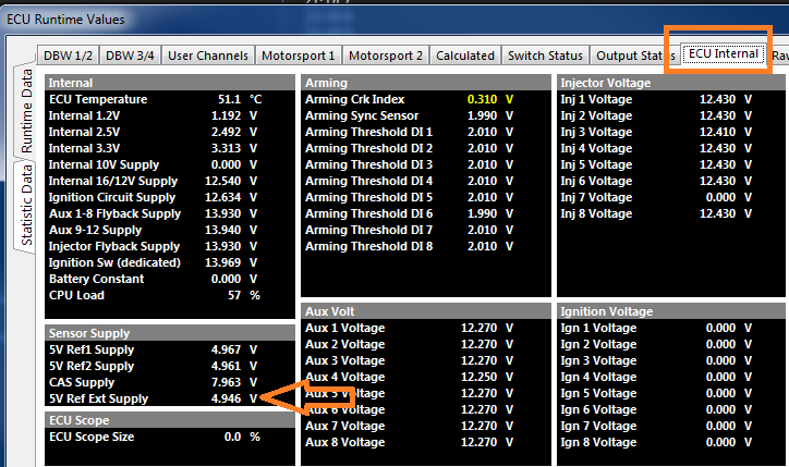
ECU Internal runtimes — the measured 5V Ref Ext Supply value used for the ratiometric correction.
Example
The following test was completed using a 3.0-Bar MAP sensor operating at barometric pressure. A comparison is shown in Table 1.0 between the Ratiometric Correction OFF and ON. With the Ratiometric Correction ON the ECU is able to generate a consistent output for variations in the sensor supply voltage.
Table 1.0 — MAP Sensor output, Ratiometric OFF/ON Comparison
| 5V Ref Supply (V) | MAP (Vref Correction OFF) | MAP (Vref Correction ON) |
|---|---|---|
| 5.000V | 99.9 kPa | 99.9 kPa |
| 4.996V | 99.8 kPa | 99.9 kPa |
| 4.975V | 99.4 kPa | 99.9 kPa |
| 4.950V | 98.8 kPa | 99.8 kPa |
| 4.900V | 98.0 kPa | 99.8 kPa |
| 4.850V | 96.8 kPa | 99.8 kPa |
| 4.700V | 93.7 kPa | 99.8 kPa |
Aux Output Notes
Emtron ECU systems have a high number auxiliary outputs on all products offered in addition to being able to utilize unused fuel and ignition channels as additional outputs. These extra outputs can be used for various functions such as solenoid control, relay control (fans, fuel pumps, etc), PWM systems, and more. Keeping with the concept of Emtron flexibility, the Aux Outputs match these needs.
Regardless of this added flexibility, careful planning for best output use is still necessary.
Aux Output Connections
SL Series ECU – 10 Aux Outputs
Auxiliary 1-4: Low side
Outputs rest at 0V when ECU is powered off
Outputs are open when not being commanded on
Low side control of relays, solenoids, lights, etc
Auxiliary 5-8: High side/Low side
Outputs rest at 0V when ECU is powered off

Outputs are open when not being commanded on regardless of polarity

    Low side or high side control of relays, solenoids, lights, etc
Auxiliary 9-10: Half bridge (DC motor control – DBW)
Outputs rest at 0V when ECU is off

Outputs command the opposite polarity when off

    IE – High side output as commanded on is low side when off
KV Series ECU – 16 Aux Outputs
Auxiliary 1-8: High side/Low side
Outputs rest at 0V when ECU is powered off
Outputs are open when not being commanded on/off regardless of polarity

    Low side or high side control of relays, solenoids, lights, etc
Auxiliary 9-16: Half bridge (DC motor control – DBW – Aux 9-12 KV8 ONLY)
Outputs rest at 0V when ECU is off
Outputs command the opposite polarity when off

            IE – High side output as commanded on is low side when off
** KV8 Aux 13-16 cannot be used as DBW control, but the functionality regarding output state is the same
Common Issues
When using an Aux Output to control a low side output that is connected to constant power.
The result is the output is ON when the ECU is powered off.
See KV Series Hardware Manual - Section 3.6
This is why the control side of many systems (relays, solenoids, etc) is switched on with ignition supply (OEM).
Due to the flexibility of the output, controlling the system as High Side instead can resolve this issue.
When using a Half Bridge output on a circuit that is sensitive to reverse polarity, this can create issues with actuation if that particular output is expecting an open circuit when commanded off.
**** For output specifications (frequency, PWM, current ratings), see ECU specification sheets.**
Closed Loop and PID
The function “Closed Loop” is defined as a control system’s ability to react automatically based on a form of feedback (position, calculated value, frequency, etc).
This is usually dependent on some sort of PID strategy.
The Emtron ECU has closed loop controls for many Functions throughout the ECU.
Common functions that rely on closed loop are:
Closed Loop Lambda Control
Idle speed control
Idle Ignition Control
VVT Cam control
DBW Control
Boost Control
Launch Control - Torque Limiting
Traction Control
All Emtron PID configurations can be very comprehensive. .
Proportional Gain: controls how aggressive instantaneous correction is based on the current target error.
Correction based on proportional error
Example 1 -
Boost Target Error = 10%
P Gain Table Entry = 1.0
P Gain Correction = 10% * 1.0 = 10%
Example 2 -
Boost Target Error = 10%
P Gain Table Entry = 2.0
P Gain Correction = 10% * 2.0 = 20%
Integral gain: controls how much adaptive correction is needed over time after the application of proportional control.
The Integral Gain will multiply the gain value vs the target error at the control rate speed.
Derivative gain: controls predictive correction. It is based on the rate of change of the error.
The target error rate of change will multiply vs the Derivative gain.
A delicate balance of these values is normally needed to provide accurate and precise control of the closed loop system.
To provide more accurate closed loop control, Emtron allows values can be spanned in 3D to allow a look up table to actively adjust based on whatever runtime is desired.
This allows the user to fine tune the closed loop functions without just relying on the target error solely.
Feed forward functions
The feed forward value allows the PID function to operate with greater accuracy if drive duty can be predicted.
Min/Max limits
These are used to clamp the PID functional range if necessary.
Enumerations
Subsections of Enumerations
Active Center Differential
| Value | Status |
|---|---|
| 0 | Disabled |
| 1 | OFF |
| 2 | ON |
| 3 | OFF - RPM Lockout |
| 4 | OFF - User Lockout |
| 5 | OFF - Timeout |
| 6 | OFF - ACD I/P not selected |
| 7 | OFF - ACD Input in Fault |
| 8 | ON - Bleed Override |
| 9 | OFF - Bleed Override Timeout |
| 10 | OFF - Bleed Override Waiting … |
| 11 | OFF - Timeout Retry Delay |
Boost Status
0    OFF

1    ON

2    ET Lockout

3    TP Lockout

4    MAP Lockout

5    RPM Lockout

6    Re-Entry Delay

7

8    OFF- RPM Zero

9    Func. Disabled

10    X No O/P Channel

11    X No Input Source

12    OFF - MAP Sensor Fault

13    OFF - MAP Limit

14    ON-Open Loop

15    ON-Mass Flow Limit
Closed Loop Fuel Status
| Value | Status |
|---|---|
| 0 | OFF |
| 1 | ON |
| 2 | OFF - Post Start |
| 3 | OFF - Eng. Temp |
| 4 | OFF - RPM Lo |
| 5 | OFF - RPM Hi |
| 6 | OFF - Rate(hz) = 0 |
| 7 | OFF - Waiting.. La1 |
| 8 | OFF - Waiting.. La2 |
| 9 | OFF - ORB Active |
| 10 | OFF - Limiting on |
| 11 | - |
| 12 | X - Input in Fault |
| 13 | OFF - La1 Input Error |
| 14 | OFF - La2 Input Error |
| 15 | X - Lam 1 Input OFF |
| 16 | X - Lam 2 Input OFF |
DBW PID Status
0    OFF

1    ON

2    Min DC Clamp

3    Max DC Clamp

4    -  Int Clamp

5    +  Int Clamp

6    Deadband
DBW System Status
0    OFF

1    ON

2    DBW + OP Err.

3    DBW - OP Err.

4    Main Relay Err.

5    OP Freq low Err.

6    TP 1 Sensor Err.

7    TP 2 Sensor Err.

8    PP 1 Sensor Err.

9    PP 2 Sensor Err.

10    Calibrating ....

11    Calibrate RPM Err.

12    Calibrate Complete

13    Disabled: RPM=0

14    Safety shutdown

15    TEST Mode

16    OFF: DBW2 in Cal
Engine Protection Status
| Value | Status |
|---|---|
| 0 | Disabled |
| 1 | OFF |
| 2 | ON |
| 3 | OFF - PostStart |
| 4 | ON - User Lockout |
| 5 | Cut Exit in progress |
| 6 | Waiting: Exit Conds |
Highest Priority Fuel/Ign Cut Status
| Value | Status |
|---|---|
| 0 | OFF |
| 1 | RPM Limit 1 |
| 2 | RPM Limit 2 |
| 3 | RPM Limit 3 |
| 4 | MAP Limit 1 |
| 5 | MAP Limit 2 |
| 6 | Ground Speed 1 |
| 7 | Ground Speed 2 |
| 8 | DBW 1 Limit |
| 9 | DBW 2 Limit |
| 10 | Launch Limit |
| 11 | Gear Cut Limit |
| 12 | Limp Home 1 |
| 13 | Limp Home 2 |
| 14 | Anti-Lag Ign Cut |
| 15 | Anti-Lag Cooldown |
| 16 | Traction Limit |
| 17 | Gear Rev-match Limit |
| 18 | Gearshift Limit |
| 19 | Rolling Launch Limit |
| 20 | ORFC |
| 21 | Oil Pressure Limit |
| 22 | Fuel Pressure Limit |
| 23 | EGT Limit |
| 24 | Engine Temp Limit |
| 25 | VDC - Engine Cut |
ORFC Status
| Value | Status |
|---|---|
| 0 | Disabled |
| 1 | ON |
| 2 | OFF |
| 3 | Lockout - TP/PP |
| 4 | Lockout - RPM |
| 5 | Lockout - Speed |
| 6 | Lockout - Downshift |
| 7 | Lockout - ECT |
| 8 | Lockout - Startup |
Traction Control Status
| Value | Status |
|---|---|
| 0 | Disabled |
| 1 | OFF |
| 2 | Armed - %Slip Drive |
| 3 | OFF -Post Start Delay |
| 4 | OFF- RPM Lo |
| 5 | OFF- RPM Hi |
| 6 | OFF- TPS Lo |
| 7 | OFF- TPS Hi |
| 8 | OFF- Slip Lo |
| 9 | OFF-RPM Zero |
| 10 | OFF-User |
| 11 | OFF - TC Sw OFF |
| 12 | Armed - %Slip Outputshaft |
VVT System Status
| Value | Status |
|---|---|
| 0 | Disabled |
| 1 | I/P Pin Not Selected |
| 2 | O/P Pin Not Selected |
| 3 | Startup Lockout |
| 4 | ET Lockout |
| 5 | RPM Lockout |
| 6 | User Lockout |
| 7 | No Signal |
| 8 | Sync Error |
| 9 | |
| 10 | |
| 11 | |
| 12 | |
| 13 | Setting VVT Offset |
| 14 | Pulse Count High |
| 15 | Pulse Count Low |
| 16 | Error: 1st VVT Signal |
| 17 | Error: 2nd VVT Signal |
| 18 | Error: 3rd VVT Signal |
| 19 | Error:4th VVT Signal |
| 20 | Error: 6th VVT Signal |
| 21 | Error: 7th VVT Signal |
| 22 | Error: 9th VVT Signal |
| 23 | Error: 10th VVT Signal |
| 24 | Error: 11th VVT Signal |
| 25 | Error:12th VVT Signal |
| 26 | |
| 27 | |
| 28 | Active |
Fault Modes & DTC Codes
The ECU monitors the relationship between the Servo Positions 1/2 signals, Pedal Positions 1/2 signals and Target vs Actual Plate Position. When an error occurs the ECU will generate the following DTC’s
- P1574 Throttle Position Sensor Disagreement between Sensors
- P1577 Pedal Position Sensor Disagreement between Sensors
- P1570 DBW Target Tracking Error
- P1581 DBW Shutdown
The DTC code will be cleared automatically by the ECU when the fault condition is removed. However, an error counter will be incremented so the fault history can be viewed.
During an active DBW DTC the ECU will limit the engine speed for safety reasons. There are several options available using the DBW Fault Mode setting:
- Non adjustable engine limit set at 2000RPM.(Recommended setting)
- Use Limp Home Table1. This is an adjustable 3D table.
- Use Limp Home Table2. This is an adjustable 3D table.
When using the Limp Home Tables make sure these are setup correctly.
Wiring References
Subsections of Wiring References
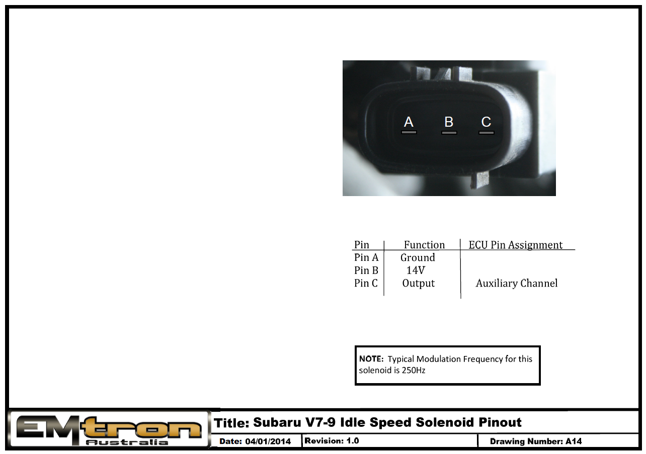
V7-V9 & H6 ISC Pinout - Subaru
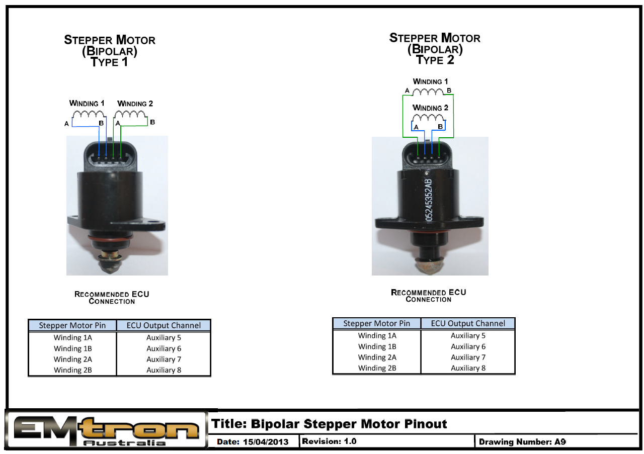
Bipolar Stepper Motor Pinout - Delco
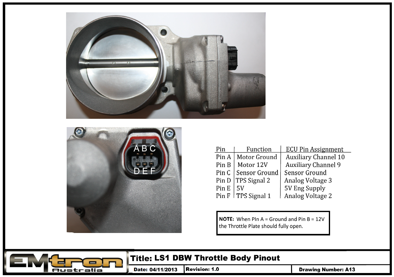
LS1 DBW Throttle Body Pinout
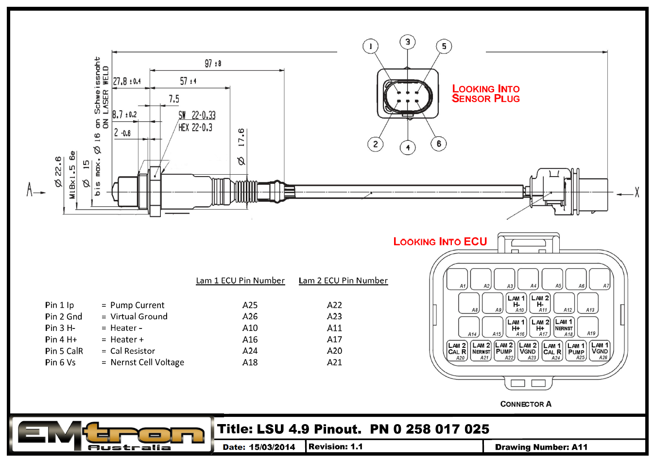
LSU 4.9 Pinout
Magnetic-Resistive Sensor Wiring
Magneto-Resistive Sensors
Magneto-resistive (MR) sensors are commonly used in driver assistance systems such as ABS, TCS and ESP to measure wheel speed, the frequency being proportional to the rotational speed of the wheel. These sensors detect a magnetic field and because there is no electrical contact the sensor can operate across a relatively large air gap. The amplitude of the output signal does not depend on speed.
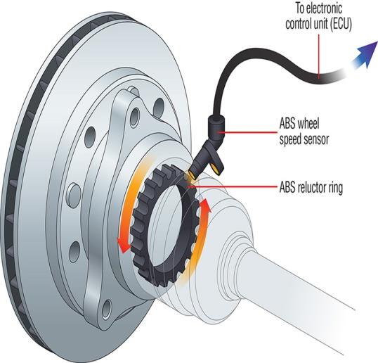
A typical MR wheel speed sensor reading an ABS reluctor ring.
These are active sensors which means they become “active” when a power supply is connected to it and a digital output waveform is then generated. However, the signal does not switch to ground like a conventional Hall sensor. Instead the signal swings between a high and low voltage, with the swing voltage dependant on the current passing through the sensor, i.e. the value of the pullup or pulldown current limiting resistor. Typical currents required to make the sensor operate are 4 – 8mA.
Two important checks must be completed.
- The polarity of the sensor must be correct.
- The pullup/pulldown resistor might need adjustment to ensure the digital signal swings within the correct levels.
Sensor Polarity
The sensor polarity can be determined by measuring the diode voltage drop across the sensor (sensor resistance cannot be used) using a Multimeter. The direction with the highest voltage drop is the correct polarity. See Table 1.0 as an example. Pin 1 should be connected to the pullup resistor and pin 2 should be connected to the ground.
Table 1.0
| Diode Voltage Drop | Pin 1 | Pin 2 | Notes |
|---|---|---|---|
| 1.781 V | Positive | Negative | Correct Polarity |
| 0.637 V | Negative | Positive | Incorrect Polarity |
Device Connection
A Magneto-resistive sensor can be connected directly to an Emtron ECU and the internal Scope function can be used to view the signal. Once you have the signal image, the arming threshold can be set correctly.
Sensor Supply and Wiring
The sensor is powered through a pullup resistor. The minimum supply voltage is 8V, ideally a regulated supply should be used to ensure consistent readings. The figure below illustrates how the sensor should be wired.
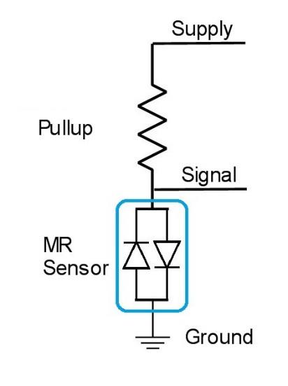
MR sensor wiring — powered through a pullup resistor from the supply, with the signal taken between the pullup and the sensor.
NoteNOTE If the pullup resistor is too big there will be insufficient current to make the output switch. Typical Pullup resistor range is 330 Ohms to 1000 Ohms. The ECU has a 4k7 pullup resistor which may not activate the sensor. In this situation an external pullup will need to be fitted.
The Low and High output levels will vary with different sensors, so for signal integrity each sensor output should be checked using an oscilloscope. Table 1.1 shows some typical results from a Toyota Sensor. Figure 1.0 shows a scope trace of an MR Sensor with 330R pullup supplied at 8V. The High Output level is 5.9V and the Low Output Level is 3.6V.
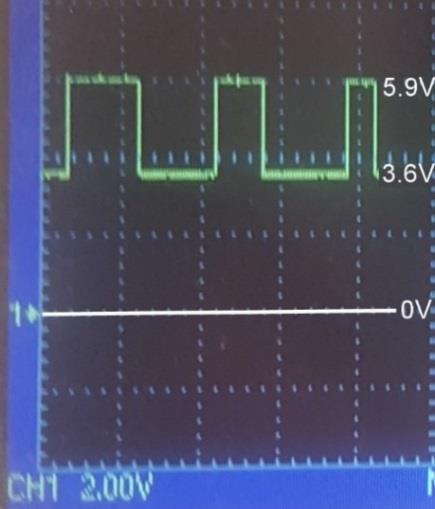
Figure 1.0 — Scope of an MR sensor (330R pullup at 8V): High output 5.9V, Low output 3.6V, against the 0V reference.
Table 1.1
| Supply | Pullup Resistance | Low Output | High Output | Switching Range | Comments |
|---|---|---|---|---|---|
| 5V | 330 Ohms | 5.2V | 5.2V | 0.0V | Insufficient Current |
| 8V | 330 Ohms | 3.6V | 5.9V | 2.3V | (see Figure 1.0) |
| 12V | 330 Ohms | 7.6V | 9.9V | 2.3V | |
| 8V | 470 Ohms | 5.25V | 5.25V | 0.0V | Insufficient Current |
| 12V | 470 Ohms | 6.3V | 9.45V | 3.15V |