Magnetic-Resistive Sensor Wiring
Magneto-Resistive Sensors
Magneto-resistive (MR) sensors are commonly used in driver assistance systems such as ABS, TCS and ESP to measure wheel speed, the frequency being proportional to the rotational speed of the wheel. These sensors detect a magnetic field and because there is no electrical contact the sensor can operate across a relatively large air gap. The amplitude of the output signal does not depend on speed.
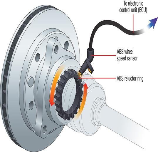
A typical MR wheel speed sensor reading an ABS reluctor ring.
These are active sensors which means they become “active” when a power supply is connected to it and a digital output waveform is then generated. However, the signal does not switch to ground like a conventional Hall sensor. Instead the signal swings between a high and low voltage, with the swing voltage dependant on the current passing through the sensor, i.e. the value of the pullup or pulldown current limiting resistor. Typical currents required to make the sensor operate are 4 – 8mA.
Two important checks must be completed.
- The polarity of the sensor must be correct.
- The pullup/pulldown resistor might need adjustment to ensure the digital signal swings within the correct levels.
Sensor Polarity
The sensor polarity can be determined by measuring the diode voltage drop across the sensor (sensor resistance cannot be used) using a Multimeter. The direction with the highest voltage drop is the correct polarity. See Table 1.0 as an example. Pin 1 should be connected to the pullup resistor and pin 2 should be connected to the ground.
Table 1.0
| Diode Voltage Drop | Pin 1 | Pin 2 | Notes |
|---|---|---|---|
| 1.781 V | Positive | Negative | Correct Polarity |
| 0.637 V | Negative | Positive | Incorrect Polarity |
Device Connection
A Magneto-resistive sensor can be connected directly to an Emtron ECU and the internal Scope function can be used to view the signal. Once you have the signal image, the arming threshold can be set correctly.
Sensor Supply and Wiring
The sensor is powered through a pullup resistor. The minimum supply voltage is 8V, ideally a regulated supply should be used to ensure consistent readings. The figure below illustrates how the sensor should be wired.
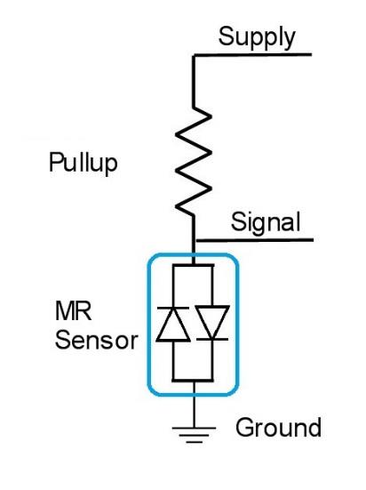
MR sensor wiring — powered through a pullup resistor from the supply, with the signal taken between the pullup and the sensor.
NoteNOTE If the pullup resistor is too big there will be insufficient current to make the output switch. Typical Pullup resistor range is 330 Ohms to 1000 Ohms. The ECU has a 4k7 pullup resistor which may not activate the sensor. In this situation an external pullup will need to be fitted.
The Low and High output levels will vary with different sensors, so for signal integrity each sensor output should be checked using an oscilloscope. Table 1.1 shows some typical results from a Toyota Sensor. Figure 1.0 shows a scope trace of an MR Sensor with 330R pullup supplied at 8V. The High Output level is 5.9V and the Low Output Level is 3.6V.
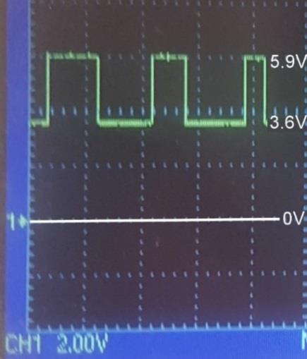
Figure 1.0 — Scope of an MR sensor (330R pullup at 8V): High output 5.9V, Low output 3.6V, against the 0V reference.
Table 1.1
| Supply | Pullup Resistance | Low Output | High Output | Switching Range | Comments |
|---|---|---|---|---|---|
| 5V | 330 Ohms | 5.2V | 5.2V | 0.0V | Insufficient Current |
| 8V | 330 Ohms | 3.6V | 5.9V | 2.3V | (see Figure 1.0) |
| 12V | 330 Ohms | 7.6V | 9.9V | 2.3V | |
| 8V | 470 Ohms | 5.25V | 5.25V | 0.0V | Insufficient Current |
| 12V | 470 Ohms | 6.3V | 9.45V | 3.15V |