Torque Modelling
The engine torque produced by combustion is calculated by the ECU using modelled algorithms and is referred to as Ideal Engine Torque. The moving parts inside the engine assembly create drag and therefore limit the torque available. The estimate of torque required to overcome this drag effect is called Frictional Loss.
The ECU also produces a calculation for Driver Demand Torque using a weighted mathematic model from multiple inputs. This is explained more in the Driver Demand Torque topic below.
The Engine Torque and Driver Demand Torque calculations have no correlation and operate independently. Both calculations will merge and track very closely, however the accuracy of these calculations will depend on the accuracy of the engine setup and mapping: i.e Injector Data, Fuel Density, VE Model etc. The ECU calculates Torque in the units of Newton-metre (Nm).
The Engine Torque and Driver Demand Torque data can be transmitted over the CAN bus in some OEM applications, which is another reason the accuracy of the calculation is important.
Engine Torque (Nm)
The Primary data source for calculating Engine Torque is the Final Air Mass (g/s) entering the engine. The Final Air Mass will be heavily influenced by VE table and Injector charachterisation so this data must be as accurate as possible to ensure the accuracy of the Engine Torque calculation.
Ideal Engine Torque is caclulated using the following inputs:
- Final Air Mass (g/s)
- Throttle Area
- Lambda Target
- Stoichiometric Ratio
- Number of cylinders
Uncorrected Engine Torque is calculated by accounting for the frictional loss of the engine. It is named “uncorrected” because other inputs can further change the Engine Torque. An Engine Torque Correction factor can also be applied and is described further down the page.
Final Engine Torque accounts for the additional inputs that can reduce or increase Engine Torque such as:
- Engine Cutting (Reduce Engine Torque)
- Ignition Retard (The Torque Model assumes the engine has the Ignition tuned for peak torque, so any retard will therefore reduce Engine Torque)
- Throttle (Throttle Mass Flow function(s) can close the throttle plate, reducing the Air Mass and hence Engine Torque. For example VDC control)
- Nitrous (This will increase Engine Torque)
Driver Demand Torque (Nm)
The Driver Demand Torque is the torque requested by the driver, primarily as a function of engine speed and pedal position to give a requested throttle area. We know through mathematical modeling that from throttle area we can calculate airflow and from airflow we can calculate torque.
Apart from some specific exceptions, the engine torque must be controlled by the driver. Some exceptions include: downshifts, traction control (VDC event), pit lane speed limiter and cruise control.
The driver only has control of torque by using the pedal, but other factors get included into the mathematical model to give a final Driver Demand Torque. These include:
- Engine Speed
- Throttle Area and Diameter
- Engine VE
- Charge Temperature
- Boost Target (Used as peak load indicator)
- Lambda Target
- Number of cylinders
All those parameters get included in a complex mathematical model which generates a runtime called Driver Demand Torque Ideal.
Accounting for frictional loss of the engine the final Driver Demand Torque can be expressed as:
Boost Target Table
It is worth mentioning the Boost Target and how the Boost Target table should be setup to help generate a more accurate Driver Demand Torque. The Y-Axis or load axis should be set to “Throttle Area Demand - Pedal” and not the raw Pedal Position Sensor.
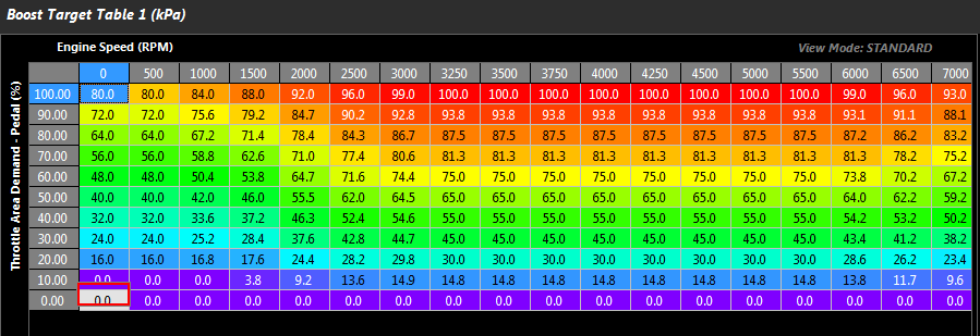
Nissan GT-R R35 Boost Target table.
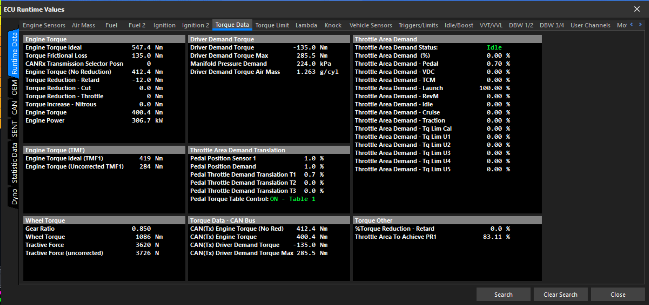
Torque Runtime Data
Engine Torque and Driver Demand Torque data is available in the Runtime Values(F3) > Torque Data tab.
Torque Limit Ignition Retard Scaling Table
This table calibrates the torque reduction % per degree. When a torque request is applied the ECU will calculate how much retard is required to achieve this torque request.
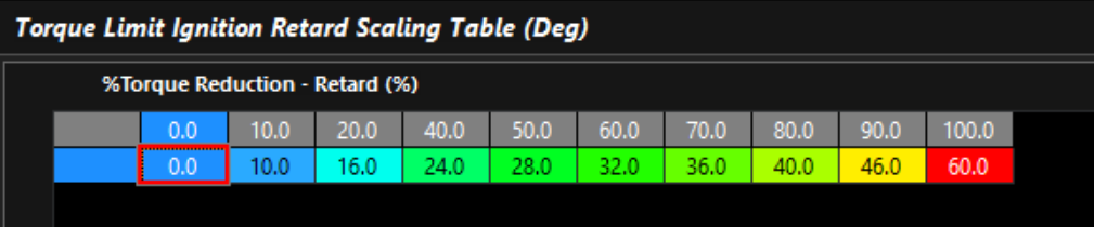
Typical Torque Reduction Ignition Retard Gain Table
In a wide variety of applications, the default table shown above will give very useable results.
Torque Limit Cut Gain Table
This table calibrates the torque reduction % per %cut. When a torque request is applied the ECU will calculate how much cut is required to achieve this torque request.
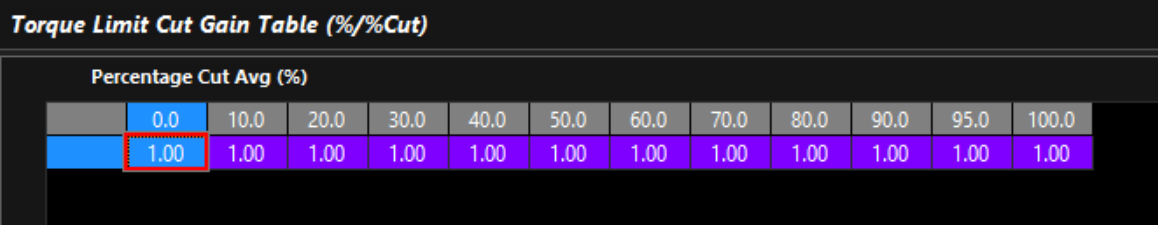
Typical Torque Reduction Cut Gain Table
Torque Corrections
Firstly, the Engine Torque values must be validated on a dyno to ensure the ECU Torque Calculation (Engine Torque Ideal, Engine Torque), are close to the values being produced on the dyno.
Note: If using a dyno where wheel power is reducing values, then this error must be factored in.
A properly tuned engine, with no error in the basic fuel model is the first step. Having proper injector data, engine displacement, fuel type/stoich, and a tuned VE table will already calculate accurate engine torque.
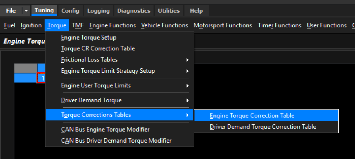
Engine Torque Correction Table
If engine torque is not calculating accurately, you can correct the torque calculation via the Engine Torque Correction Table.
Tip: A value of 1.0 = no correction.
Driver Demand Torque Correction Table
Driver Demand channel is used in some OEM applications, but also can be used as a channel in the ECU to feed forward the driver tour requests. The Driver Demand can be corrected via the Driver Demand Torque Correction Table.
Tip: A value of 1.0 = no correction.