Subsections of Air Mass Tuning
Air Mass Model Compensation
Overview
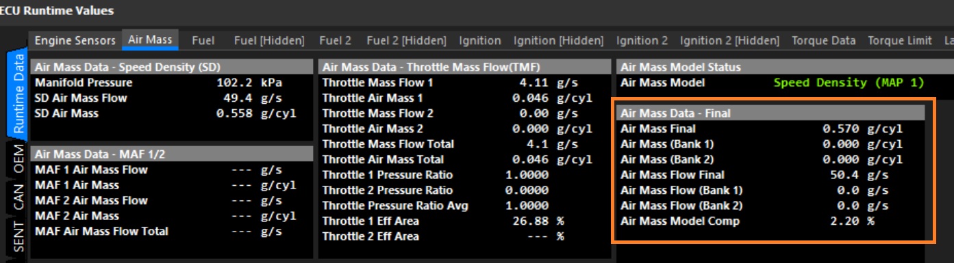
The Air Mass Model Compensation applies a percentage adjustment to the calculated Final Air Mass. The resulting Air Mass Final value can be viewed in F3 Runtime → Air Mass. The Air Mass Model Comp (%) value applied to the calculation is also displayed here.
The Air Mass Model Compensation function is enabled from Config → Air Mass → Air Mass Model Setup.
In the example below, Speed Density calculates an Air Mass of 0.558 g/cyl. A 2.20% compensation is then applied, resulting in a Air Mass Final of 0.570 g/cyl.
This 3D table can be used to compensate for engine operating conditions that are not fully represented by the selected Air Mass Model, improving air mass accuracy across the operating range.
The compensation is applied AFTER the primary air mass calculation has been completed.
- 0.0% = No compensation applied
- Positive values = Increase calculated air mass
- Negative values = Decrease calculated air mass
Note:
The Air Mass Compensation Table should not be used to compensate for incorrect VE calibration or sensor scaling errors. These should be corrected at their source wherever possible.
The X and Y axes of the Air Mass Comp Table are fully configurable and may be assigned to any suitable ECU runtime. This allows the compensation to be tailored to the specific engine and application.
Units: Air Mass Flow is expressed in units of g/s (grams per second), while Air Mass is expressed in units of g/cyl (grams per cylinder), representing the mass of air trapped in the cylinder during a single engine cycle
Air Mass Model Blend Table
Background
The Air Mass Model defines how the ECU calculates the mass of air entering the engine. The calculated air mass is then used to determine the required fuel mass to achieve the commanded Lambda Target, before being converted into an injector pulse width using the configured injector characteristics.
Different engine combinations may benefit from different air mass calculation strategies. Emtron provides several Air Mass Models to suit a wide range of applications.
Options
| Value | Air Mass Model |
|---|---|
| 0 | Speed Density (MAP) |
| 1 | Speed Density (BAP) |
| 2 | Mass Air Flow (MAF) |
| 3 | Air Mass Modelled + Throttle Mass Flow (TMF) Blend |
| 4 | Speed Density (MAP) + Throttle Mass Flow (TMF) Blend |
| 5 | Emtron Air Mass Model (Custom) |
When Air Mass Model 3, 4 or 5 is selected, the Air Mass Blend Table becomes active. The Air Mass Blend Table is a three-dimensional calibration table that determines the contribution of each selected Air Mass Model to the final calculated engine air mass.
The table output is expressed as a percentage, where:
- 0% = 100% Primary Air Mass Model
- 100% = 100% Secondary Air Mass Model
- Intermediate values proportionally blend the two Air Mass Models.
This allows the ECU to transition smoothly between two air mass calculation methods as engine operating conditions change, combining the advantages of each model over different areas of the operating range.
Air Mass Modelled + Throttle Mass Flow (TMF) Blend
(Option 3)
- 0.0% → 100% Air Mass Modelled
- 50.0% → Equal blend of both models
- 100.0% → 100% Throttle Mass Flow (TMF)
Speed Density (MAP) + Throttle Mass Flow (TMF) Blend
(Option 4)
- 0.0% → 100% Speed Density (MAP)
- 50.0% → Equal blend of both models
- 100.0% → 100% Throttle Mass Flow (TMF)
Emtron Air Mass Model
(Option 5)
- 0.0% → 100% **Calculation 1
- 50.0% → Equal blend of both models
- 100.0% → 100% **Calculation 2
Note
The X and Y axes of the Air Mass Blend Table are fully configurable and may be assigned to any suitable ECU runtime. This allows the blend ratio to be tailored to the specific engine and application.
Manifold Pressure Estimate Table
Overview
The Manifold Pressure Estimate calculates a theoretical manifold pressure independently of the measured Manifold Pressure (MAP) sensor.
The calculated pressure can be used in several applications:
- MAP Sensor Fallback – The estimated manifold pressure can be used as a fallback when a MAP sensor fault is detected.
- Transient Air Mass Calculation – The estimated manifold pressure can be blended with the measured MAP during high transient conditions. This can improve the air mass calculation response and reduce the reliance on Acceleration Enrichment.
- Individual Throttle Body (ITB) Applications – The estimated manifold pressure can be used as a calculated MAP source on engines where a conventional MAP sensor is not fitted or where the MAP signal is unreliable.
Note
The X and Y axes of this Table are fully configurable and may be assigned to any suitable ECU runtime.
Exhaust Pressure Estimate Table
Overview
The Exhaust Pressure Estimate calculates a theoretical exhaust manifold pressure independently of an Exhaust Manifold Pressure (EMAP) sensor. This allows the VE Expansion Ratio correction to operate without relying on a continuously measured EMAP signal.
Due to the harsh operating environment of an EMAP sensor, sensor failures can occur. The EMAP Estimation Table can be filled with measured exhaust pressure data and then used as an alternative pressure source.
Once calibrated, the estimated exhaust pressure can be used as a fallback in the event of an EMAP sensor failure, allowing the VE Expansion Ratio correction to continue operating.
Note
The X and Y axes of this Table are fully configurable and may be assigned to any suitable ECU runtime.