Fuel VE Tables
Overview
The fueling calculations used by Emtron are based on an Air Mass per cycle which is then converted to a Fuel Mass based on the requested lambda target. This is true whether the system is using directly measuring airflow from the air mass meter, or calculated air mass from speed density or throttle mass flow (TMF)
The Volumetric Efficiency (VE) table is used when the Air Mass Model is configured for Speed Density.
In Speed Density mode, the ECU does not directly measure the engine airflow. Instead, it calculates the air mass entering each cylinder using the Ideal Gas Law based on:
- Engine Displacement
- Manifold Absolute Pressure (MAP)
- Charge Temperature
- Volumetric Efficiency (VE)
The calculated Air Mass per Engine Cycle is then used to determine the required Fuel Mass based on the commanded Lambda Target. The ECU then converts the required fuel mass into an injector pulse width using the configured injector characteristics.
ℹ️ Note
The ECU supports one or two Volumetric Efficiency (VE) tables. The active table configuration is selected using the VE Table Control setting, which determines whether a single VE table is used or whether blending between two VE tables is enabled (Z- Axis).
Volumetric Efficiency (VE) Table
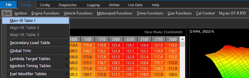
The Volumetric Efficiency (VE) table represents the engine’s ability to fill its cylinders with air under varying engine speeds and loads.
Although referred to as Volumetric Efficiency (VE), the ECU uses VE to determine the air mass trapped within the cylinder. VE is expressed as a percentage and represents the ratio of the actual air mass trapped within the cylinder to the theoretical air mass that would occupy the engine’s swept cylinder volume under standard atmospheric conditions.
The calculated air mass is then used by the ECU to determine the required fuel mass to achieve the commanded Lambda Target.
A higher VE indicates the engine is filling its cylinders more efficiently, requiring more fuel to maintain the commanded Lambda Target.
Most engines typically operate below 100% VE.
ℹ️ Note
The term Volumetric Efficiency is historical and can be misleading. While VE is expressed as a percentage of the cylinder’s theoretical filling, the ECU ultimately uses the VE value to calculate the air mass entering the cylinder. Since fuel delivery is based on air mass rather than air volume, VE is simply a convenient way of modelling the engine’s air pumping efficiency.
Due to intake and exhaust tuning, pressure wave dynamics and scavenging effects, a well-designed naturally aspirated engine can exceed 100% VE over parts of its operating range.
Tuning
Before calibrating the VE table(s), the Lambda Target table(s) should first be configured with the desired lambda or air-fuel ratio for each operating condition.
Once the Lambda Target table(s) have been calibrated, the VE table is adjusted until the measured lambda matches the commanded Lambda Target. The two tables are intrinsically linked, the Lambda Target defines the desired result, while the VE table determines the amount of fuel required to achieve it.
For more information, refer to the Lambda Target Tables.
Typical Values
Typical VE values vary depending on engine design and operating conditions.
- Idle: 35–40%
- Engines at full load: 80–100%
- High-performance naturally aspirated engines: 90–110% (typical peak)
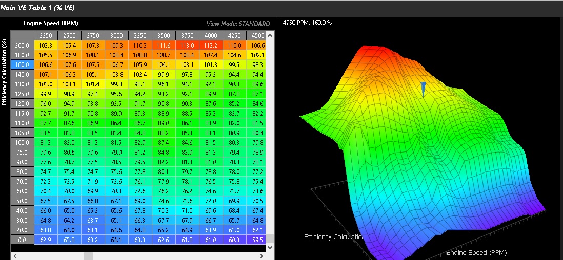 The above VE table example shows the typical range of values.
🔧Tuning Notes
- The VE table is calibrated by adjusting its values until the measured lambda matches the commanded Lambda Target across the engine’s operating range.
- This process is most efficient when the ECU is configured with a Wideband Lambda input, allowing the measured lambda to be compared directly with the commanded target.
- Once the VE table has been correctly calibrated, the engine’s volumetric efficiency model has been established, providing an accurate basis for fuel delivery calculations.
- The objective is to minimise the error between the measured lambda and the Lambda Target under all operating conditions.
- A simple method of validating the VE calibration is to change the Lambda Target at a specific operating point. If the VE table and injector characterization have been calibrated correctly, the measured lambda should follow the new Lambda Target without requiring further VE adjustments.
- If changes to the VE table are required to achieve the new Lambda Target, this may indicate an error in the VE calibration or the configured injector characterization (injector flow, deadtime, or non-linearity).
- When Closed Loop Lambda Control is enabled, the VE table provides the feed-forward fuel calculation, while the closed loop controller applies only the corrections necessary to eliminate any remaining fueling error.
VE Table Control
This control determines whether a single target table is used or whether Z-axis blending is enabled between two calibration tables.
Available Options
| Value | Mode |
|---|---|
| 0 | OFF |
| 1 | ON - Table 1 |
| 2 | ON - Table 2 |
| 3 | Not Available |
| 4 | Not Available |
| 5 | Cal Slot |
| 6 | ON - Z-Axis |
Mode Descriptions
OFF (0)
Disables the Lambda Target table input
ON - Table 1 (1)
Uses VE Table 1 only for air masss speed density model
ON - Table 2 (2)
Uses VE Table 2 only for air masss speed density model
Not Available (3–4)
Reserved for future functionality and should not be selected.
Cal Slot (5)
Enables real-time switching of the Fuel VE tables via calibration slot selection.
This allows the ECU to switch between pre-defined calibration sets without modifying the Table Control setting. See Tuning view -> Cal Control menu
Dual VE tables are particularly useful for engines with significantly different airflow characteristics between operating modes. For example, on a Honda VTEC engine, one VE table can be calibrated for the low-lift cam profile and the second VE table calibrated for the high-lift cam profile. Once both tables have been tuned across the full operating range, the VTEC changeover point can be adjusted to determine the optimum switching RPM without requiring the VE calibration to be retuned.>
Example application:
- Table 1 = VTEC Low-lift Cam
- Table 1 = VTEC high-lift Cam
The active table can be switched in real time based on RPM or a user defined switch condition
ON - Z-Axis (6)
The Z-Axis enables a user-defined third axis used to swap or blend between VE Table 1 and VE Table 2.
The ECU performs real-time linear interpolation between both VE tables based on the configured Z-Axis input. This allows fuel delivery to be dynamically adjusted across a third operating dimension, which can be spanned using any available runtime parameter within the ECU.
- 0% Z-axis → 100% Table 1
- 100% Z-axis → 100% Table 2
- Intermediate values → linear interpolation between both tables
For a Fuel Tuning Overview see: Fuel Tuning Overview