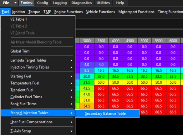
Secondary Injection Balance Table
Overview
The Secondary Balance Table defines how the total fuel required for each injection event is divided between the Primary and Secondary injectors.
Table values are expressed as a percentage (%) and represent the proportion of the total fuel volume delivered by the Secondary injectors. The remaining fuel is automatically delivered by the Primary injectors.
Table Values
| Value | Fuel Distribution |
|---|---|
| 0% | 0% Secondary injectors, 100% Primary injectors |
| 50% | Equal fuel volume delivered by the Primary and Secondary injectors |
| 100% | 100% Secondary injectors, 0% Primary injectors |
Intermediate values proportionally divide the required fuel between the Primary and Secondary injectors.
ℹ️ Note
The Secondary Balance Table controls the fuel volume distribution between the Primary and Secondary injectors. The ECU automatically calculates the individual injector pulse widths based on the injector flow rates and the configured Secondary Balance value to achieve the required total fuel delivery.
When the Primary and Secondary injector flow rates are correctly configured and calibrated, changing the Secondary Balance value should have little or no effect on the overall engine air-fuel ratio
Example 1:
Operating Conditions
- Primary Injector = 1000 cc/min
- Secondary Injector = 1000 cc/min
- Required Total Injector Flow = 20.000 ms
Balance Table = 50.0%(Equal flow from both injectors):
Primary Injector Flow = 10.000ms Secondary Injector Flow = 10.000msBalance Table = 25.0%( 25% of the flow supplied from Sec Injectors):
Primary Injector Flow = 15.000ms Secondary Injector Flow = 5.000msBalance Table = 75.0%( 75% of the flow supplied from Sec Injectors):
Primary Injector Flow = 5.000ms Secondary Injector Flow = 15.000ms
Example 2:
Operating Conditions
- Primary Injector = 1000 cc/min
- Secondary Injector = 2000 cc/min
- Required Total Injector Flow = 20.000 ms
Balance Table = 50.0%(Equal flow from both injectors):
Primary Injector Flow = 10.000ms Secondary Injector Flow = 5.000msBalance Table = 25.0%( 25% of the flow supplied from Sec Injectors):
Primary Injector Flow = 15.000ms Secondary Injector Flow = 2.500msBalance Table = 75.0%( 75% of the flow supplied from Sec Injectors):
Primary Injector Flow = 5.000ms Secondary Injector Flow = 7.500ms
⚠️ Note
Ideally you want to adjust the the Balance Table so the pulse width and hence duty cycle is the same for both Primary and Secondly Injectors. To calculate the Balance value use the following formula:
Secondary Balance (to achieve equal Prim/Sec Pulse Widths)
Where:
Example
Using the data from the above Example 2:
Secondary Balance (to achieve equal Prim/Sec Pulse Widths):
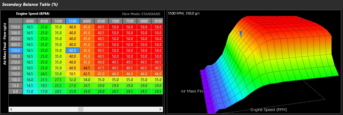
The above example is from a Mitsubishi EVO IX with staged injectors
Getting creative…
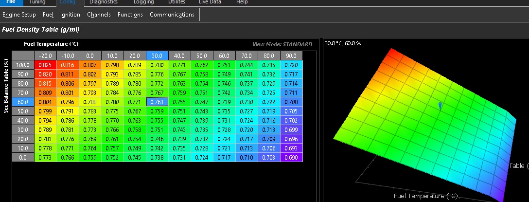
In the case where 2 separate fuel systems are utilized with 2 different fuel types. Example: Gasoline and Methanol
The secondary balance table becomes the runtime the fuel density change is spanned across in the main fuel configuration
See Gasoline to Methanol examples below
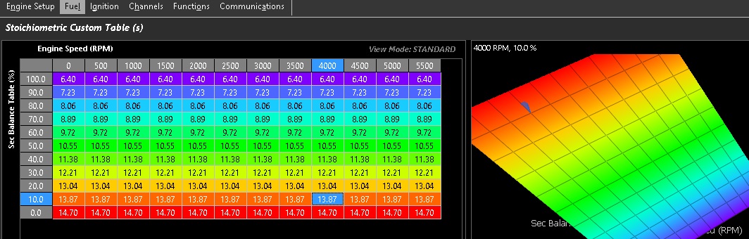
The Stoichiometric custom table should also be spanned across the secondary blend runtime in this application.