Subsections of Ignition Tuning
Ignition Main Tables
The Ignition Tables are the primary ignition calibration used by the ECU and define the base ignition timing as a function of engine speed and load.
The table values represent the desired ignition timing in degrees Before Top Dead Centre (BTDC) and are typically indexed by Engine Speed (RPM) and Engine Load.
The ECU uses the active Ignition Table as the starting point for all ignition calculations before applying additional ignition corrections, compensations, torque reduction strategies (Strat Modes) to determine the final commanded ignition timing.
Specifications
- Units: Degrees BTDC
- Minimum Value: -100.0 Deg
- Maximum Value: 100.0 Deg
Function Behaviour
- Higher values command more ignition advance.
- Lower values command less ignition advance.
- A value of 0.0 Deg represents no ignition advance before TDC.
- Negative ignition timing values represent ignition after TDC (ATDC)
The final ignition timing delivered by the ECU may be modified by additional ignition corrections and compensations, including:
- Global Ignition Trim
- Coolant Temperature Compensation
- Intake Air Temperature Compensation
- Knock Control
- Idle Ignition Control
- Ignition Retard Torque Reductions via User Torque Limits and Strat Modes
- Other configured ignition corrections
Important Note - Ignition Timing Synchronisation
Before calibrating the Ignition Table, the ECU ignition timing must be synchronised with the actual engine crankshaft position.
See the overview below or view : Crank Index Overview for more help.
To verify synchronisation:../../config/triggers/crank-index-offset-setup.md
- Enable Ignition Lock and set a fixed ignition timing value (Ignition Lock Angle).
- Use a timing light to measure the actual ignition timing at the engine.
- Compare the timing light reading with the configured Ignition Lock Angle.
- Adjust the Crank Index Offset until the timing light reading matches the Ignition Lock Angle. This test should be completed at idle.
- Next, verify the ignition timing as engine speed is increased while adjusting the Ignition Delay Time. Correct Ignition Delay Time calibration ensures the commanded ignition timing accurately matches the actual crankshaft position across the complete engine speed range.
Adjustment guidelines:
- If the measured ignition timing retards as engine speed increases, increase the Ignition Delay Time value.
- If the measured ignition timing advances as engine speed increases, decrease the Ignition Delay Time value.
Once synchronised, disable Ignition Lock and the ECU will accurately command the ignition timing values defined by the Ignition Table and associated ignition corrections.
WARNING
Incorrect ignition synchronisation will result in the ECU commanding ignition timing that does not match the actual engine timing, which can lead to poor engine performance or engine damage.
Global Ignition Trim
This function applies a global ignition timing trim across all ignition channels.
The configured trim value is added to the final calculated ignition timing after all other ignition corrections and compensations have been applied. The trim is applied uniformly across all operating conditions and is independent of engine speed (RPM) and load.
Specifications
- Units: Deg
- Minimum Value: -100.0 Deg
- Maximum Value: +100.0 Deg
Function Behaviour
- Positive values advance ignition timing.
- Negative values retard ignition timing.
- A value of 0.0 Deg applies no global ignition correction.
WARNING
This function is intended as a quick global adjustment to the overall ignition timing.
For permanent calibration changes, adjust the appropriate ignition timing table(s) or compensation map(s). Do not use the Global Ignition Trim as a substitute for proper ignition calibration or long-term corrections.
Compensations
All Ignition Compensations (within the Ignition Tab) are raw degree values added/subtracted onto the Ignition Base Angle Calculation :
Cylinder Trims
Cylinder Trims can be enabled for each cylinder to adjust a timing +/- in a 3D table
Idle Ignition Control
Base Idle Ignition Table
Defines the base ignition angle of the idle ignition control.
This table can be expanded into a 3D look up table using any runtime for axis.
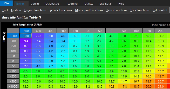
Above example shows the table spanned using Idle Target error & dRPM
- Idle Target error references Idle Speed Control Main Idle Target table
** dRPM is the engine Speed rate of change
Ignition Advance Clamp
Ignition Advance Clamp
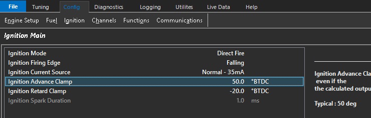
The maximum ignition advance allowed even if the the calculated output is higher.
Typical : 50 deg
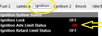
The ECU also provides a Status flag to indication this condition. Open the ECU Runtimes menu (F3) and select the Ignition Tab.
Ignition Advance Rate Table
Ign Advance Rate Table
Globally controls how fast the rate of advance can be applied by the ECU
Units = Degrees/sec
Example:
Ign Advance Rate Table = 500/sec
Ignition Advance Rate of Change = 500 degrees/sec
** This function/parameter is always active
Ignition Main Table Z-Axis Setup
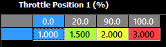
Z-Axis uses a separate X axis lookup that can allow the blending of all the available tables.
Ignition Retard Rate Table
Ign Retard Rate Table
Globally controls how fast the rate of retard can be applied by the ECU
Units = Degrees/sec
Example:
Ign Retard Rate Table = 500/sec
Ignition Retard Rate of Change = 500 degrees/sec
** This function/parameter is always active
Ignition Table Control
Table Control
Emtune has multiple tables for many engine functions. The table behaviour is based on comprehensive selections in Tuning under the respective function (IE, Fuel, Ignition, DBW, Cam control). Some functions have many tables that can be enabled such as Fuel and Ignition tabs. These main functions allow you to enable a variety of compensations, modifiers, individual trims, and more.
For main table controls, the selections are mostly universal.
(Fuel example shown)
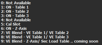
Not all of the above example will be available for every function, but generally most functions are the same.
**ON – Table *** enable those respective tables always.
Cal Slot enables which table is currently being commanded by the Cal Slot Control (see Cal Slot Control)
Z-Axis uses a separate X axis lookup that can allow the blending of all the available tables.
Any runtime can be used, and the units equal which table to run in this case. You can see in the above example the ECU will switch (and interpolate in between) the three different tables available based on TP1 position.
*** Blend** tables allow switching between two tables only.
Transient Ignition
Transient Ignition
Tuning transient functions in Emtune is done through a combination of function setup and table settings.
The following runtimes are generated which are applied/added/subtracted to final base Ignition calculations.
- Ignition Rate of Change – The current ignition rate of change in degrees per second
- Ign Accel Trim – Ignition retard trim being added by accel trim function
- Ign Decel Trim – Ignition advance trim being added by decal trim function
Transient Ignition Setup
Tuning -> Ignition -> Transient -> Ignition Transient Setup
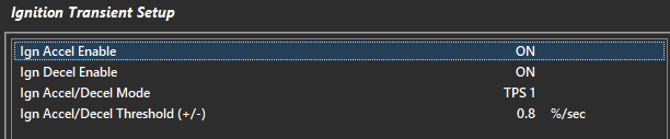
Enable functions
Turn on and off Accel and/or Decel modes here.
Ign Accel/Decel Mode
Choose pedal position, throttle position, or MAP sensor to initiate the function. This configures what runtime the threshold lockout looks at.
Accel/Decel Threshold (+/-)
The minimum rate of change required to initiate the accel/decel function – related to Acce/Decel Mode
Ign Accel Sens Table
Control the amount of Ignition Accel Retard for a given Rate of Change.
Ignition Accel Retard = Rate of Change x Sens.
Example:
dTP1 = 5.0%/sec
Sens = 4.5
Ignition Retard = 5.0%/sec * 4.5 = 22.5 of ignition retard.
Ign Accel Clamp Table
Clamps the maximum amount of accel timing allowed by accel ignition.
Example:
Accel Clamp = 10 degrees (retard)
Ignition base angle = 35 degrees
Ignition angle = 25 degrees
Ign Accel Decay Table
Controls the percentage Ign Accel Decay per Engine Cycle
Example:
Ign Accel = -10.0 Retard start value
Ign Decay = 10.0%.
Ignition Accel will decay back to zero at 1.0 degree per engine cycle.
Ign Decel Sens Table
Control the amount of Ignition Decel Advance for a given Rate of Change
Ignition Decel Advance = Rate of Change x Sens.
Example:
dTP1 = 8.0%/sec
Sens = 1.5
Ignition Advance = 8.0 %/sec x 1.5 = 12.0 of ignition advance
Ign Decel Clamp Table
Clamps the Maximum Ignition Decel Advance
Example:
Accel Clamp = 10 degrees (advance)
Ignition base angle = 20 degrees
Ignition angle = 30 degrees
Ign Decel Decay Table
Controls the percentage Ign Decel Decay per Engine Cycle
Example:
Ign Decel = 10.0 Adv start value
Ign Decay = 10.0%.
Ignition Decel will decay back to zero at 1.0 degree per engine cycle.