Throttle Body Area Table
Overview
The Throttle Body Area Table is a 40-cell calibration table that defines the relationship between Throttle Plate Position (Servo Position) and the corresponding effective Throttle Area.
The table describes how much effective area is available for air to flow through the throttle body at each throttle plate position. This relationship is determined by the physical design of the throttle body and is not linear.
The ECU uses this relationship to:
- Convert a Pedal Throttle Area demand into the corresponding Servo Position used as the DBW Target.
- Determine the effective throttle area available at a given Servo Position for Throttle Mass Flow (TMF) calculations.
Accurate calibration of this table is critical to Throttle Mass Flow calculations and therefore to ECU functions that depend on accurate throttle airflow estimation, including:
- Idle Control
- Cruise Control
- Torque Management
- Throttle Control
- Air Mass Modelling
See the TMF Tuning help topic for more information on Throttle Mass Flow Tuning.
Example:
Pedal Throttle Area Demand = 4.37%
Using the table in the below image, the ECU would find the 4.37% area and correlate this to 9.0% Servo Position. The DBW Servo Position Target therefore becomes 9.0%
i.e the ECU is asking for 4.37% area and moves the throttle plate to 9.0% servo position to achieve this.
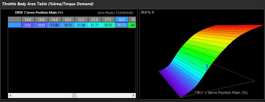
Nissan GT-R R35 Throttle Body Area table is shown above.
**Throttle body templates are also available to load into the ECU from the File -> Import Module File menu
There are multiple ways to calibrate the appropriate throttle area.
Method 1 – MAF verification
If the application is using a calibrated MAF sensor. Then the throttle area % can be adjusted and matched to TMF air mass VS MAF air mass at different throttle/DBW servo positions.
Method 2 – Matching Lambda
If no MAF sensor is available, setting fuel trims to 0 (or near 0), you can adjust the throttle area to match the target mixture very quickly.
** The only way to truly validate error in the TMF calculation is to use Method 1
** Some extreme applications where live Lambda is unstable may be more difficult to map with Method 2
Tunining Tip
Per the Matching Lambda validation method, the Throttle Area Table can be quickly tuned while the engine is operating in TMF. Adjust the table values at the relevant throttle areas until the measured Lambda matches the Lambda Target Table for the corresponding operating conditions.
Before performing this validation:
- Turn Wideband Lambda Control off.
- Set the TMF Blend Bias to 100% TMF.
Adjusting the Throttle Area Table changes the effective throttle area used by the TMF model and therefore the calculated airflow. When the measured Lambda consistently matches the Lambda Target Table across the operating range, the Throttle Area Table has been practically validated for engine operation in TMF.
See Torque Management Tuning Guide, Throttle Mass Flow, and Torque Reduction (throttle) sections for more specific information, and guides on how to tune.