Throttle Mass Flow Tuning
Overview
Throttle Mass Flow (TMF) as the name indicates, is the rate at which air mass is flowing through a throttle body in units of grams/second (g/s). Using the throttle body size, throttle area, temperature, pre and post throttle pressures,the ECU can very accurately calculate air flow through the throttle body and therefore into the engine; this is known as the TMF Calculation. Other sensors that also generate air mass flow (g/s) data are Manifold Pressure and MAF sensors. The TMF Calculation is just another method of determining air mass flow and has benefits over MAP and MAF as discussed further down.
The image below illustrates the basic elements required to calculate TMF.
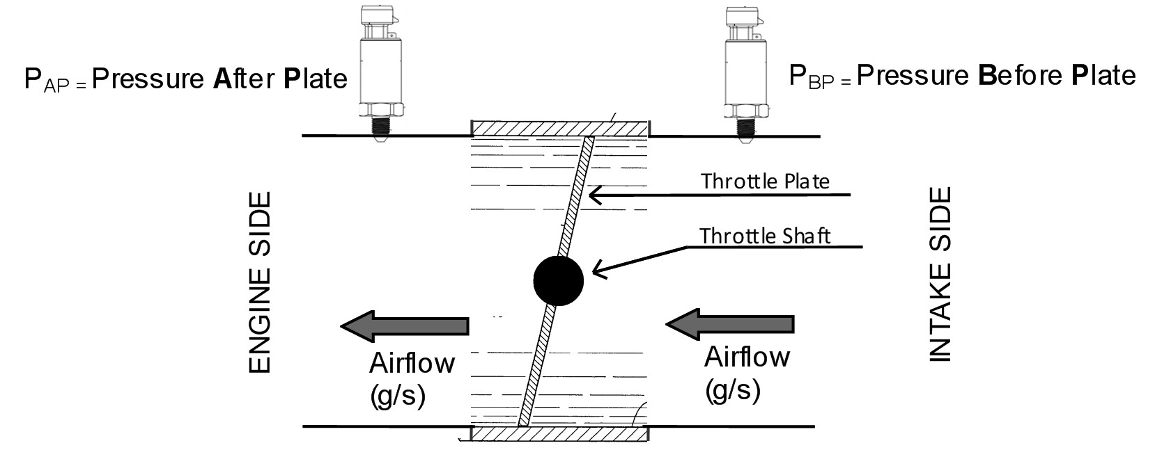
Getting into more detail, the flow through a throttle body is governed by three physical elements, Conversation of mass, Newtons second law of motion for fluids and Conservation of energy. By combining these elements the ECU can model the flow of fluid through the throttle body accounting for throttle plate thickness and throttle shaft size. By then including real-time data such as the pressure ratio across the throttle plate and the instantaneous throttle area, the ECU can precisely calculate the mass flow rate through a throttle body.
Although these calculation are complex, the TMF setup process for the user is kept as simple as possible with the following inputs and setup required:
Example: TMF Airflow Validation and Blending Workflow
Use the following workflow to validate TMF airflow, calibrate the Throttle Body Area Table, and correctly blend TMF with alternative air-mass calculation methods.
1. Base Engine Setup
Ensure the fundamental engine configuration is correct before beginning TMF calibration.
- Engine displacement
- Injector data
- Engine configuration and cylinder setup
- Other parameters required for accurate air-mass and fuel calculations
2. Throttle Body Setup
Ensure the throttle body configuration and control are correctly established.
- Correct throttle body size and configuration
- Throttle position calibration
- Throttle control PID tuning fully validated
- Throttle operation stable and repeatable across the operating range
3. Sensor Configuration and Calibration
Verify that all sensors required by the TMF model are correctly selected, assigned, calibrated, and installed.
Pre-throttle MAP
- Correct sensor assignment
- Correct calibration
- Correct physical installation and pressure reference
Post-throttle MAP
- Correct sensor assignment
- Correct calibration
- Correct physical installation and pressure reference
IAT
- Correct sensor assignment
- Correct calibration
- Correct sensor location
4. Enable and Configure TMF
Once the engine, throttle body, and sensors have been validated:
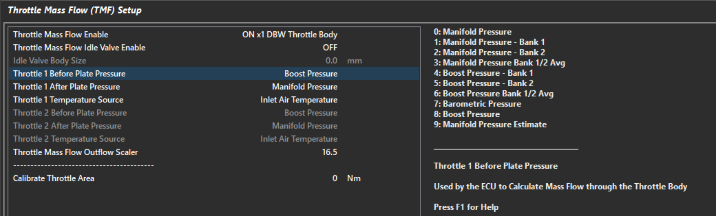
- Select and assign the correct sensors.
- Enable the TMF Air Mass Model.
- Verify that all required TMF inputs are valid and responding correctly.
- Confirm that the calculated TMF airflow is reasonable before proceeding with calibration.
5. Air Mass Model
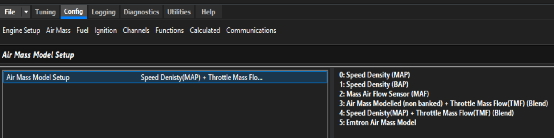
- Select the required Air Mass Model.
6. Outflow Function
The Outflow function drives the TMF calculation at pressure ratios near 1.0. See the help article on TMF Outflow for more detail.
If the Outflow Reference and Outflow Measured values are scaled correctly, the Throttle Air Mass will read very close to MAP Air Mass (speed density) as above. With correctly scaled Outflow, it’s possible to use TMF 100% of the time (though this may not always be desirable).
The main thing to tune here is the Outflow Reference Scaler:
- Outflow Reference uses (references) the VE value, so before setting the scaler, ensure that the MAP Air Mass, at least near pressure ratios of 1.0, is accurate.
- Adjust the Outflow Reference Scaler so that the Throttle Air Mass is the same as or just slightly under the MAP Air Mass.
Info
- The scaler has an inverse effect on Throttle Air Mass:
- Increasing Outflow Reference Scaler will reduce Throttle Air Mass.
- Decreasing the Outflow Reference Scaler will increase Throttle Air Mass.
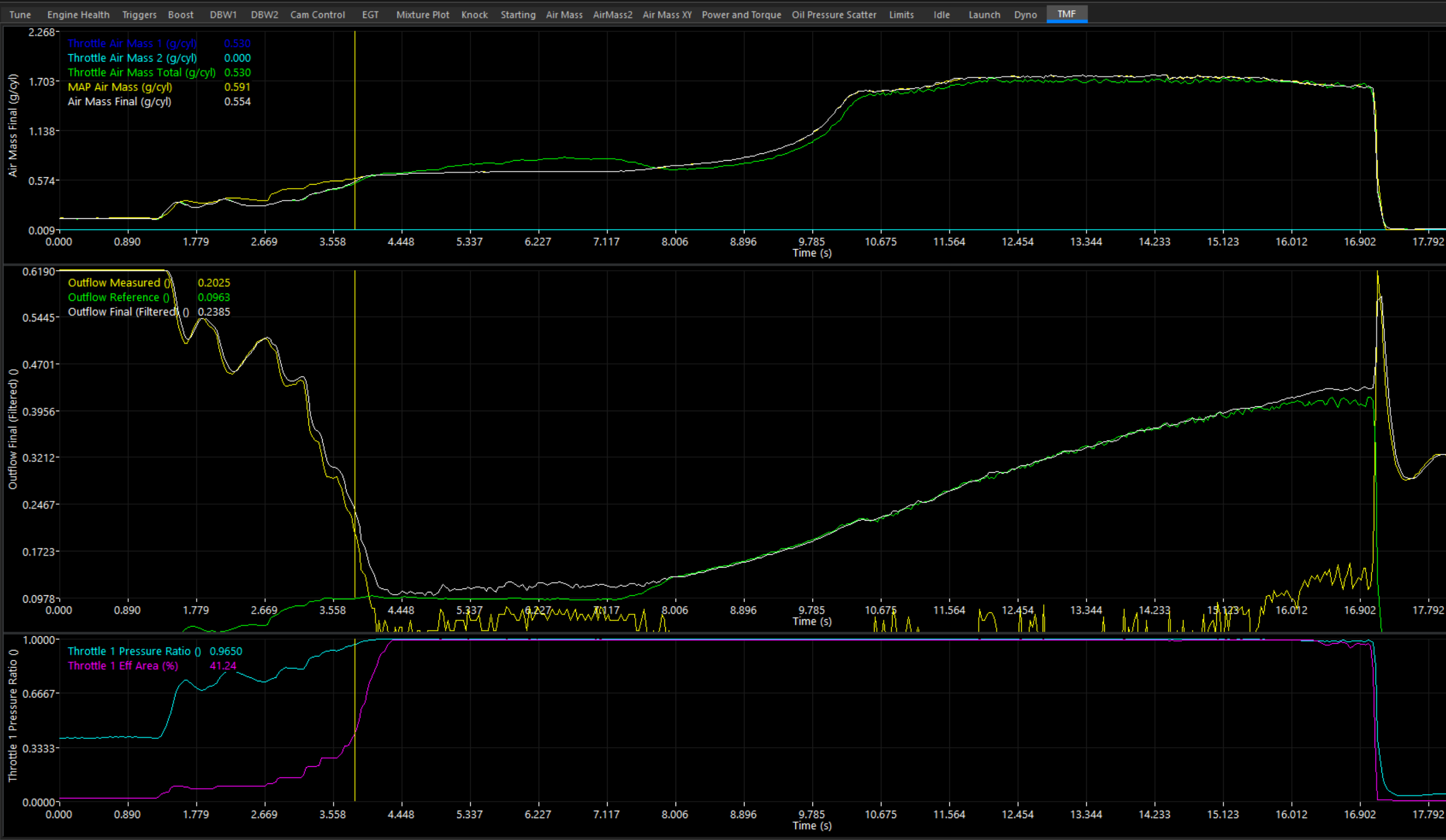
In the above image:
- At lower Throttle Effective Area & Throttle Pressure Ratio’s, Outflow Measured is highest and is driving Outflow Final.
- Near pressure ratio’s of 1.0, Outflow Reference is highest, and takes control of Outflow Final.
- At WOT, where Outflow Reference is dominant, the Reference Scaler is set so that Throttle Air Mass is very close to MAP Air Mass.
- The Air Mass Model Blending Table is dictating Air Mass Final:
- Low Throttle Area / Pressure Ratio: Air Mass Final = Throttle Air Mass.
- High Throttle Area / Pressure Ratio: Air Mass Final = MAP Air Mass.
Tip
It’s better to adjust the Reference Scaler from a full full power run log, rather than from a single stead state zone.
A correctly configured TMF Outflow Reference Scaler should also translate to torque calculations. Torque can also be used as a “compare” channel. In some cases, this allows you to validate torque calculation, frictional losses, etc - at the same time.
7. Air Mass Model Blending Table
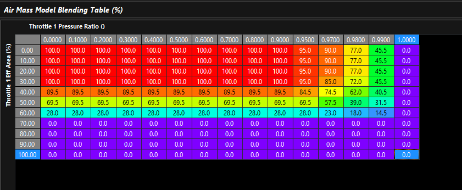
This table controls where the Air Mass Final runtime comes from:
- 0.0% = Air Mass Model Calculation 1 (eg: Speed Density)
- 100% = Air Mass Model Calculation 2 (eg: Throttle Mass FLow (TMF))
- 50.0% = Interpolate half way between Calculation 1 & Calculation 2.
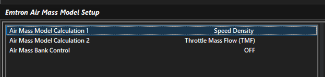
Non Conventional VE Tables
Depending on the specific application, and the throttle area demand/effective area vs pressure ratio, you may find that all of, or most of the part-throttle SD VE table is no longer necessary. This allows for non-conventional VE tuning to be used. In many cases, the entire load axis of the VE table can be turned off (or set to something other than MAP/Load) as it’s no longer needed.
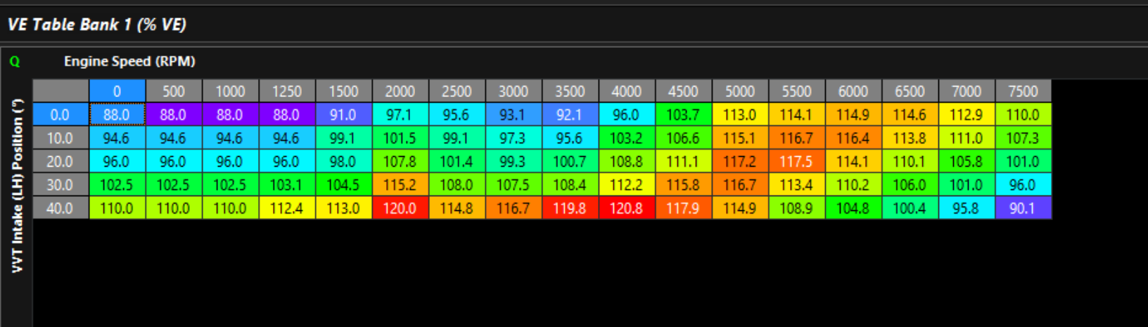
An example of a non-conventional VE table. This engine runs in TMF below WOT. As WOT approaches it blends into Speed Density. The cam position is dynamically accounted for in the VE table. The expansion ratio correction is used to account for changes in VE as boost increases.
As an added bonus, tuning this way informs the optimal cam position by following the high spots in the VE table.
8. Tuning the Throttle Body Area Table
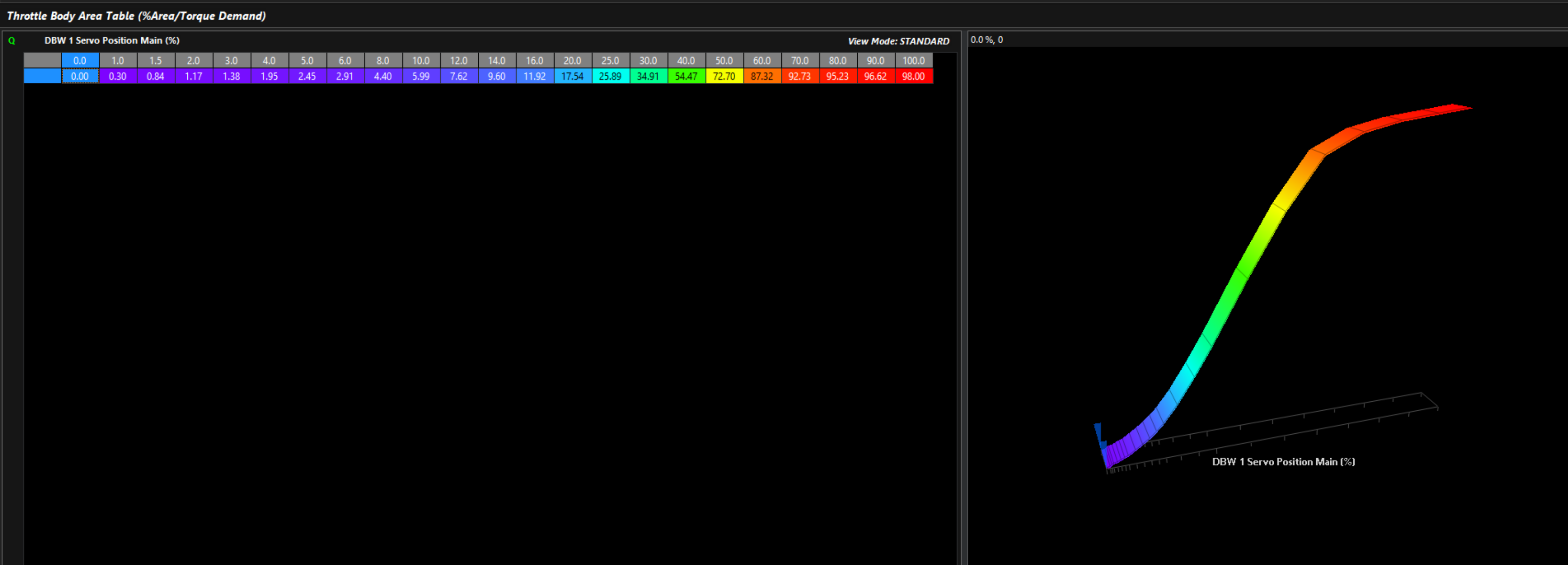 The Throttle Body Area table tells the ECU how much actual throttle area exposed to flow air at different throttle positions. The relationship to throttle position is not linear. This is key to the ECUs Torque Management functions, as accurate air mass measurement and actual engine torque go hand in hand.
For torque management, Throttle Area Demand can be manipulated which will be directly proportional to air mass when this is configured correctly
This 2D table is all that is needed to appropriately map the given throttle area vs throttle position. As mentioned previously, this allows for extremely fast and accurate mapping of the engine when TMF is active.
Important
It is important to understand that the Pedal Demand and other targeting of throttle area will target the “unit location” in this table, which will then correspond to the DBW Servo Position.
This means, there could be little relationship between Throttle Area Demand and actual DBW Servo Position on fully tuned setups.
There are multiple ways to calibrate the appropriate throttle area:
Method 1 – Matching Lambda
- Ensure fuel trims are 0 and closed loop lambda is off.
- Blend the fuel model into 100% TMF.
- Hold the engine at a stead state, high enough that air flow is reasonable stable (eg: 3000 RPM).
- Adjust the throttle area table so that measured Lambda matches Lambda Target.
Tip
Tune Speed Density at WOT first:
At higher throttle pressure ratios, where Outflow Reference is influencing Outflow Final, MAP Air Mass already be accurate or the error will be baked into the Throttle Area Table.
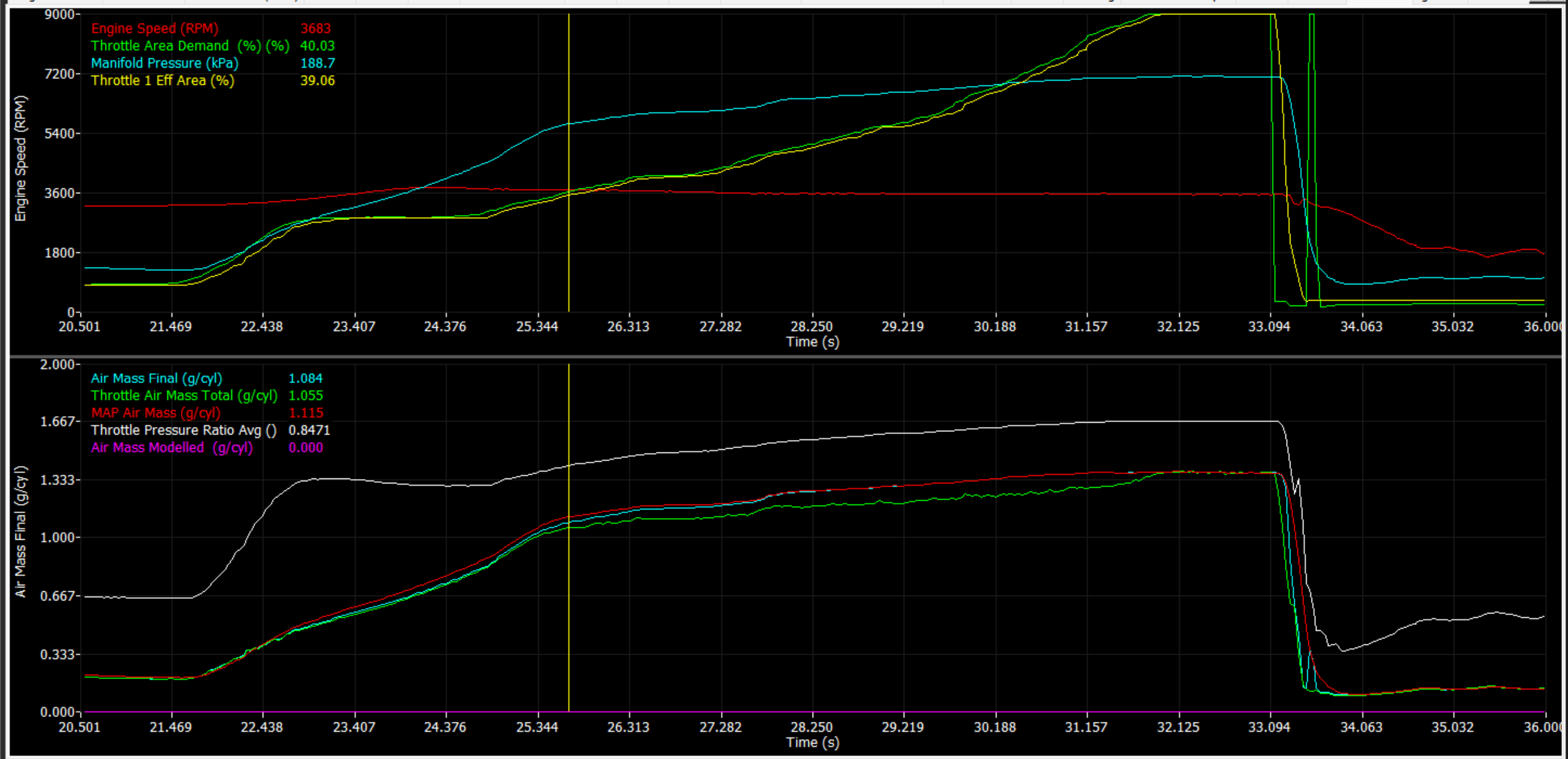
Method 2 – Matching other forms of Air Mass measurement
If the application is using a calibrated MAF sensor. Then the Throttle Area % can be adjusted and matched to so that Throttle Air Mass matches MAF Air Mass at different throttle/DBW servo positions. The same can be done matching Throttle Air Mass to MAP Air Mass.
Important
MAF and/or MAP Air Mass must be validly running the engine - running the commanded lambda target, etc.
9. Validating Throttle Area Torque
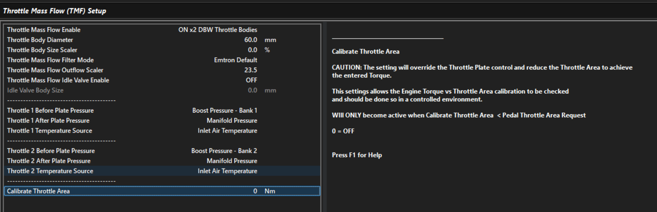
Another way to validate Throttle Area and TMF Torque, is to force the ECU into a “Torque Management” function. The Calibrate Throttle Area setting in Throttle Mass Flow Setup does exactly this. It allows you to set a fixed throttle torque limit (eg: 300nm). When this torque limit is driven into, the ECU will use TMF and the Throttle Area Table to try and limit the engine torque to the configured value.
Once a torque limit is set, the “Engine Torque TMF” channels should match the standard Engine Torque channels, otherwise the Throttle Area table is incorrect.
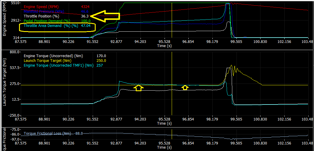
Example of where Engine Torque TMF and Engine Torque are not matching due to incorrect Throttle Area settings.
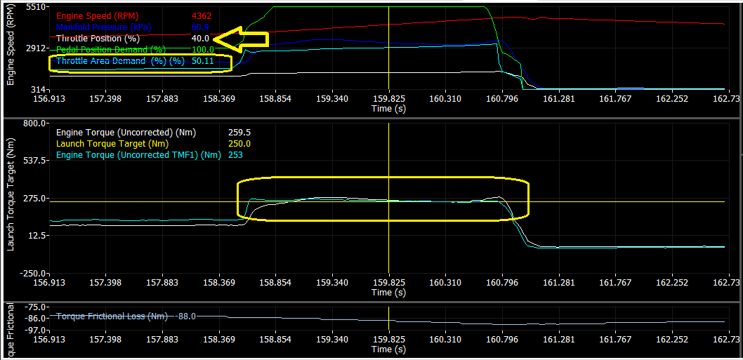
Corrected Throttle Area table so Engine Torques further aligned.
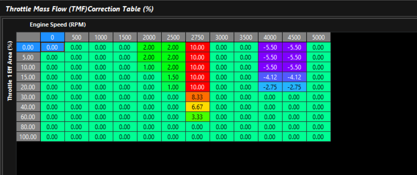
10. TMF Correction Table
This correction table essentially exists to help remove an error remaining in the system across a wide variety of load & rpm conditions. Start with the whole table set to 0, and adjust if necessary.