Torque Modelling Introduction
Introduction: Importance of Torque
Before looking at the Torque data available in the ECU, it is important to understand why Torque is such a fundamental parameter within the ECU.
The majority of the ECU functionality operates on Torque, specifically through Torque Reduction. Instead of simply applying a fixed amount of throttle closure, ignition retard or engine cut, functions such as Traction Control and Launch Control can request a specific amount of torque reduction. The ECU then uses the configured Torque Reduction Strategies (Strat Modes) to calculate how to achieve the requested reduction. These strategies are user configurable and use three primary methods to reduce torque:
- Throttle (TMF): Using the TMF Air Mass Model the ECU can calculate the throttle area required to achieve the requested torque reduction.
- Ignition Retard: Using the Ignition Retard Scaling Table, the ECU calculates the amount of ignition retard required to achieve the requested torque reduction.
- Engine Cut: Using the Cut Gain Table, the ECU calculates the amount of engine cut required to achieve the requested torque reduction.
: The ECU uses the calculations within the Engine Torque Model to precisely determine the throttle area, ignition retard or engine cut percentage required to achieve the requested torque target. The required value is calculated directly and applied instantly, rather than using a slow closed-loop process to progressively adjust the torque reduction.
: Importance of Accurate Torque Modelling
Because torque-based control functions rely on the calculated engine torque, the accuracy of the Engine Torque Model is critical. If the calculated torque does not accurately represent the actual engine torque, a requested torque reduction may not produce the expected change in engine output. This can result in torque control functions being either too aggressive or insufficient. The Air Mass Model is a primary input to the Engine Torque Model. Accurate calibration of the Air Mass Model is therefore essential for accurate torque calculation and reliable torque control.
See Torque Reduction section for more information.
For Torque Tuning information please refer to Torque Tuning.
ECU Torque Data Overview
The engine torque produced by combustion is calculated by the ECU using modelled algorithms and is referred to as Ideal Engine Torque. The moving parts inside the engine assembly create drag and therefore limit the torque available at the crankshaft. The estimated torque required to overcome this drag is called Frictional Loss.
The ECU also produces a calculation for Driver Demand Torque using a weighted mathematical model from multiple inputs. This is explained further down the page.
Important Note:
The Engine Torque and Driver Demand Torque calculations have no direct correlation and are calculated independently. Under normal operating conditions, both calculations will generally converge and track closely. The accuracy of both calculations depends on the accuracy of the engine setup and calibration, including Injector Data, Fuel Density, Air Mass Model, and other relevant parameters. The ECU calculates torque in Newton-metres (Nm).
The Engine Torque andDriver Demand Torque data can also be transmitted over the CAN bus for some OEM applications. Accurate torque modelling is therefore particularly important when responding to transmission torque reduction requests, where the transmission relies on accurate torque information and controlled torque reduction.
Engine Torque (Nm)
The primary input used to calculate Engine Torque is the Final Air Mass (g/s) entering the engine. The Final Air Mass will be heavily influenced by the Air Mass Model, the VE table and Injector charachterisation so this data must be as accurate as possible to ensure the accuracy of the Engine Torque calculation.
Ideal Engine Torque is calculated using the following inputs:
- Final Air Mass (g/s)
- Throttle Area
- Lambda Target
- Stoichiometric Ratio
- Number of Cylinders
- Compression Ratio
Compression Ratio: For a given Final Air Mass and Lambda Target, an engine with a higher Compression Ratio will generally produce more torque than an otherwise equivalent engine with a lower Compression Ratio. This is because the higher compression ratio allows the combustion process to convert a greater proportion of the available energy into useful mechanical work. The ECU applies an internal Compression Ratio Correction to account for this effect.
Uncorrected Engine Torque is calculated by accounting for the frictional loss of the engine. It is named “uncorrected” because other inputs can further change the Engine Torque. An Engine Torque Correction factor can also be applied and is described further down the page.
Final Engine Torque accounts for the additional inputs that can reduce or increase Engine Torque such as:
- Engine Cutting (Reduce Engine Torque)
- Ignition Retard (The Torque Model assumes the engine has the Ignition tuned for peak torque, so any retard will therefore reduce Engine Torque)
- Throttle (Throttle Mass Flow function(s) can close the throttle plate, reducing the Air Mass and hence Engine Torque. For example VDC control)
- Nitrous (This will increase Engine Torque)
Driver Demand Torque (Nm)
The Driver Demand Torque is the torque requested by the driver, primarily as a function of engine speed and pedal position to give a requested throttle area. We know through mathematical modeling that from throttle area we can calculate airflow and from airflow we can calculate torque.
Apart from some specific exceptions, the engine torque must be controlled by the driver. Some exceptions include: downshifts, traction control (VDC event), pit lane speed limiter and cruise control.
The driver only has control of torque by using the pedal, but other factors get included into the mathematical model to give a final Driver Demand Torque. These include:
- Engine Speed
- Throttle Area and Diameter
- Engine VE
- Charge Temperature
- Peak Manifold Pressure (Used as peak load indicator). See Torque -> Drive Demand Torque -> Peak Manifold Pressure Estimate.
- Lambda Target
- Number of cylinders
- Compression Ratio
All those parameters get included in a complex mathematical model which generates a runtime called Driver Demand Torque Ideal.
Accounting for frictional loss of the engine the final Driver Demand Torque can be expressed as:
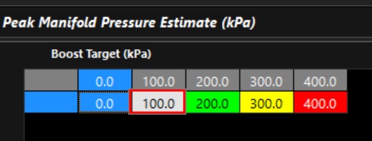
Peak Manifold Pressure Estimate Table
This is a critical parameter used in the Driver Demand calculation. The ECU compares the current Manifold Pressure against the expected peak value to determine a pressure ratio. This ratio is then used as a weighted scaler within the mathematical model to derive Driver Demand Torque.
Think of this value as a load indicator — it represents how close the engine is to its expected maximum manifold pressure.
The table can normally use 1:1 scaling, with the axis spanning the expected pressure range:
- For a normally aspirated engine this is barometric pressure.
- For a turbo charged engine this is normally the boost target.
Torque Runtime Data
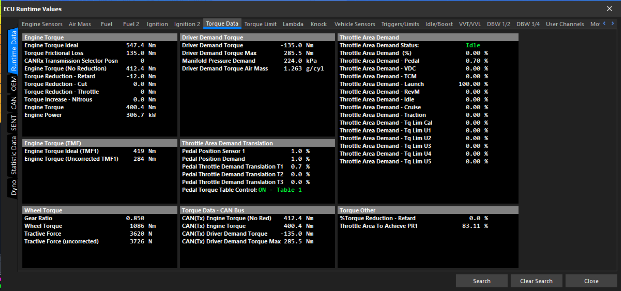
Engine Torque and Driver Demand Torque data is available in the Runtime Values(F3) > Torque Data tab.
ECU Torque Settings
See Torque Setting section for more information.
Torque Corrections
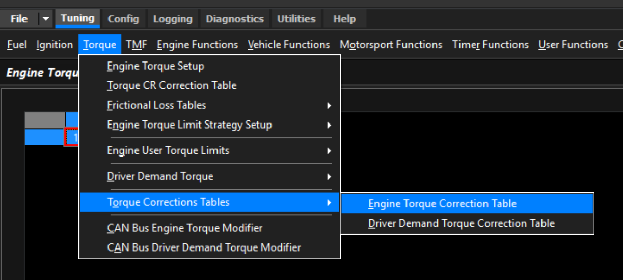
Firstly, the Engine Torque values must be validated on a dyno to ensure the ECU Torque Calculation (Engine Torque Ideal, Engine Torque), are close to the values being produced on the dyno.
Note: If using a dyno where wheel power is reducing values, then this error must be factored in.
A properly tuned engine, with no error in the basic air mass model is the first step. Having proper injector data, engine displacement, fuel type/stoich, and a tuned VE table will already calculate accurate engine torque.
Engine Torque Correction Table
If engine torque is not calculating accurately, you can correct the torque calculation via the Engine Torque Correction Table.
Tip: A value of 1.0 = no correction.
Driver Demand Torque Correction Table
Driver Demand channel is used in some OEM applications, but also can be used as a channel in the ECU to feed forward the driver tour requests. The Driver Demand can be corrected via the Driver Demand Torque Correction Table.
Tip: A value of 1.0 = no correction.