Cam Switch
Cam Switch
The Emtron ECU Cam Switch function is a comprehensive function to control simple cam switch solenoids
(VTEC, Lift solenoids, advance/retard solenoids).
Instead of just having standard switch criteria like a simple RPM or load threshold, the Emtron Cam Switch function has a series of setup functions, plus a 3D table to control its activation.
The 3D table should not be mistaken for a PWM duty table – This is not a closed loop control system.
For PWM duty control, use the VVT Cam Control function.
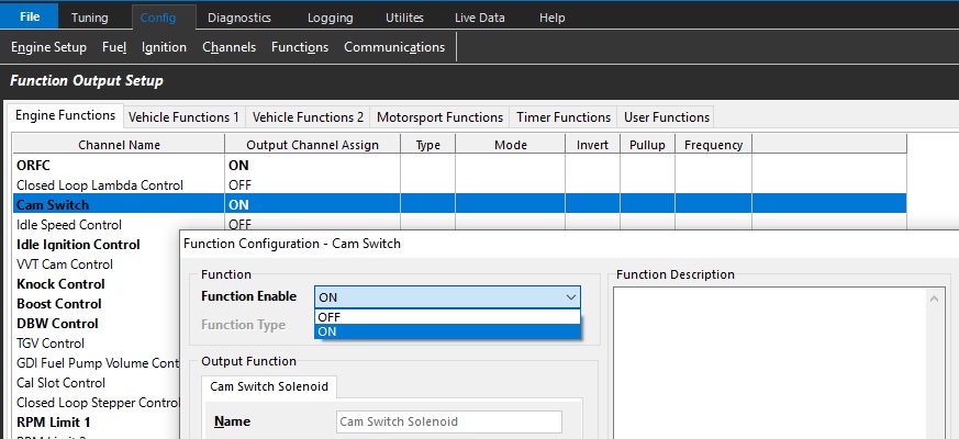
Output Setup
Output Channel Selection
Select open outputs that are appropriate for the type of Cam Switch system you are using
Driver Type
Set Low or High side function
Frequency
There should be no frequency/PWM function enabled for this function. It is a “switch” function only.
Function Setup
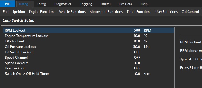
RPM Lockout
RPM above when the Cam Switch can become active. Typically 500rpm.,
Engine Temp Lockout
Temperature above when the Cam Switch can become active. Typically 20 DegC
TP Lockout
Throttle above when the Cam Switch can become active. Typically 10.0%
Oil Pressure Lockout
Oil Pressure above when the Cam Switch can become active. Only applies if Oil Pressure Input Channel has been configured.
Oil Switch Lockout
Used to ensure there is oil pressure when the Cam Switch can become active. Only applies if Oil Pressure Switch Input Channel has been configured.
Speed Channel
Select Speed Channel to be used for Speed Lockout (below)
Speed Lockout
Speed above when the Cam Switch can become active. Typically 5kph.
User Lockout
Allows the Cam Switch function to be locked out by a user function. When the User Function is ON, the lockout is active.
Switch ON -> OFF Hold Timer
When the Output has been commanded to switch OFF, this setting will keep the Output ON for the time entered. Useful for example by allowing the Output to remain ON during gearshift.
Cam Switch Table
This look-up table commands the ECU to switch the Cam Switch Output OFF, ON, or remain unchanged.
Value 0 = Cam Switch OFF
Value 100 = Cam Switch ON
Any number in between 1-99 is hysteresis mode which causes the output to remain unchanged. Typical value used is 50. This prevents the Cam Switch function output toggling ON/OFF when the mapped point is close to the edge of activation.
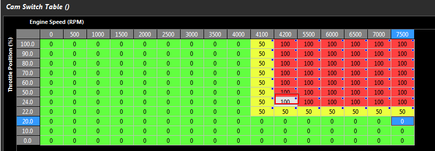
The above picture illustrates an example of how to implement hysteresis in a CAM Switch Table.
1) RPM Axis. Between 4001 and 4199 there is no output change defined by a Table value of 50. With increasing RPM at 4200 the output will Switch ON defined by a Table value of 100. With Decreasing RPM at 4000 the Output will Switch OFF defined by a Table value of 0. The result is a Hysteresis of 200 RPM
2) Throttle Position. Between 20.1% and 23.9% there is no output change defined by a Table value of 50. With increasing Throttle at 24.0% the output will Switch ON defined by a Table value of 100. With decreasing Throttle at 20.0% the Output will Switch OFF defined by a Table value of 0. The result is a Hysteresis of 4% Throttle.