Crank Index Sensor
Crank Index Sensor
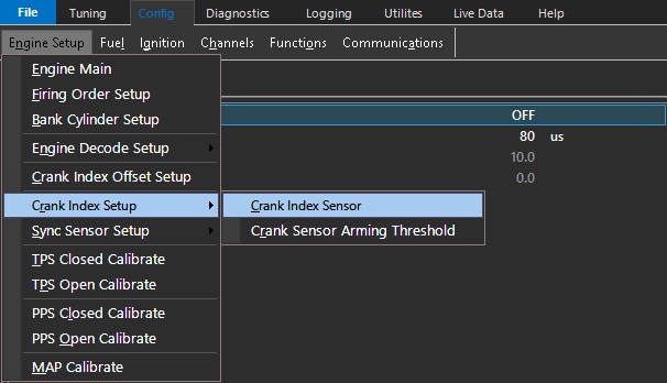
Crank Sensor Type
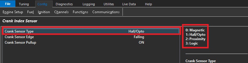
Inputting a numerical value from 0 to 2 enables setting of the crank sensor type.
0: Magnetic
1: Hall Effect or Optical Sensor
2: Proximity
3: Logic (Available in future)
Magnetic sensors are voltage generators. They produce voltage, so they will produce a sign wave signal, and generally produce higher voltages as the tone ring speed (engine speed) increases. They can be identified easily by usually having TWO WIRES only. Almost all of them will have a third wire, but this is almost always a shield wire, which must be connected to the ECU shield pin.
Wiring for Magnetic sensors is particularly sensitive, as since they can produce low voltages (especially at lower engine speeds), they can be more susceptible to interference issues. Proper wiring practices must be adhered to without fail especially with magnetic sensors. Always use the dedicated trigger input pins on the ECU (Crank +/- Sync +/-), with correct sensor polarity.
** Polarity of Magnetic sensors must be correct. See Uses of Scope - Improper Crank/Sync Sensor Polarity
Hall Effect sensors produce square wave signals. They require a voltage source (Emtron has a dedicated 8V voltage source pin for CAS), and can be identified generally by usually having THREE WIRES. Supply, signal, and ground.
Always use the dedicated trigger input pins on the ECU (Crank +/- Sync +/-)
** Do not connect Hall Effect (or any other “Pulsed” sensor grounds) to Analog Volt Ground pins
Crank Sensor Edge
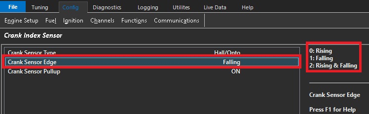
Inputting a numerical value from 0 to 2 enables setting of the crank sensor edge type.
0: Rising
1: Falling
2: Rising & Falling
Edge configuration should only be adjusted when using non Pre-Defined Engine Decoding Modes
** When Selecting ANY Pre-Defined Engine Decoding mode (3 +), Crank/Sync Sensor type, Edge configuration, Pull up configuration is all pre-configured for the user. The user should not need to adjust these.
When using any other decoding mode (1 tooth per TDC, or Multi-Tooth Custom), USE FALLING EDGE unless otherwise instructed specifically by Emtron support.
Both Magnetic and Hall effect sensors have “fast” performance when the tone ring teeth pass the sensors on falling edge consistently.
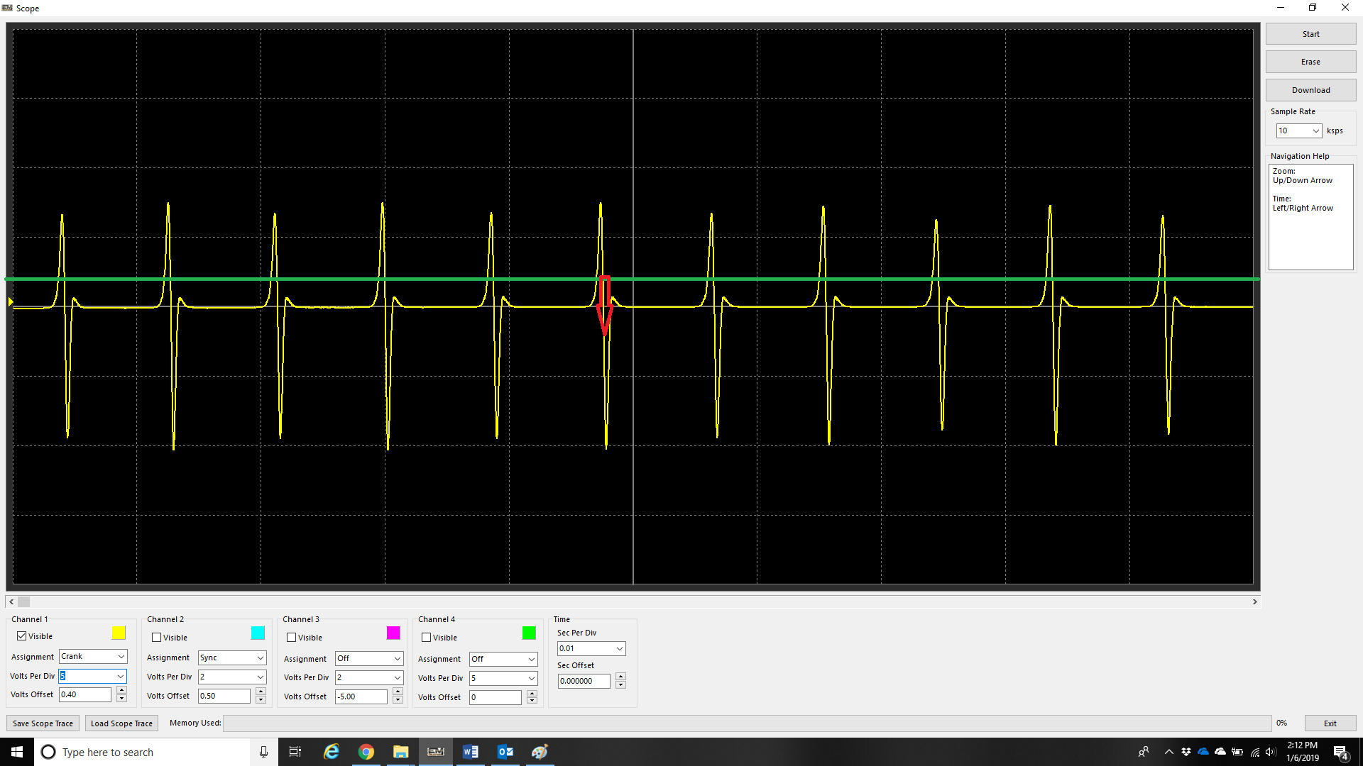
An example of a magnetic sensors fast edge being the falling.
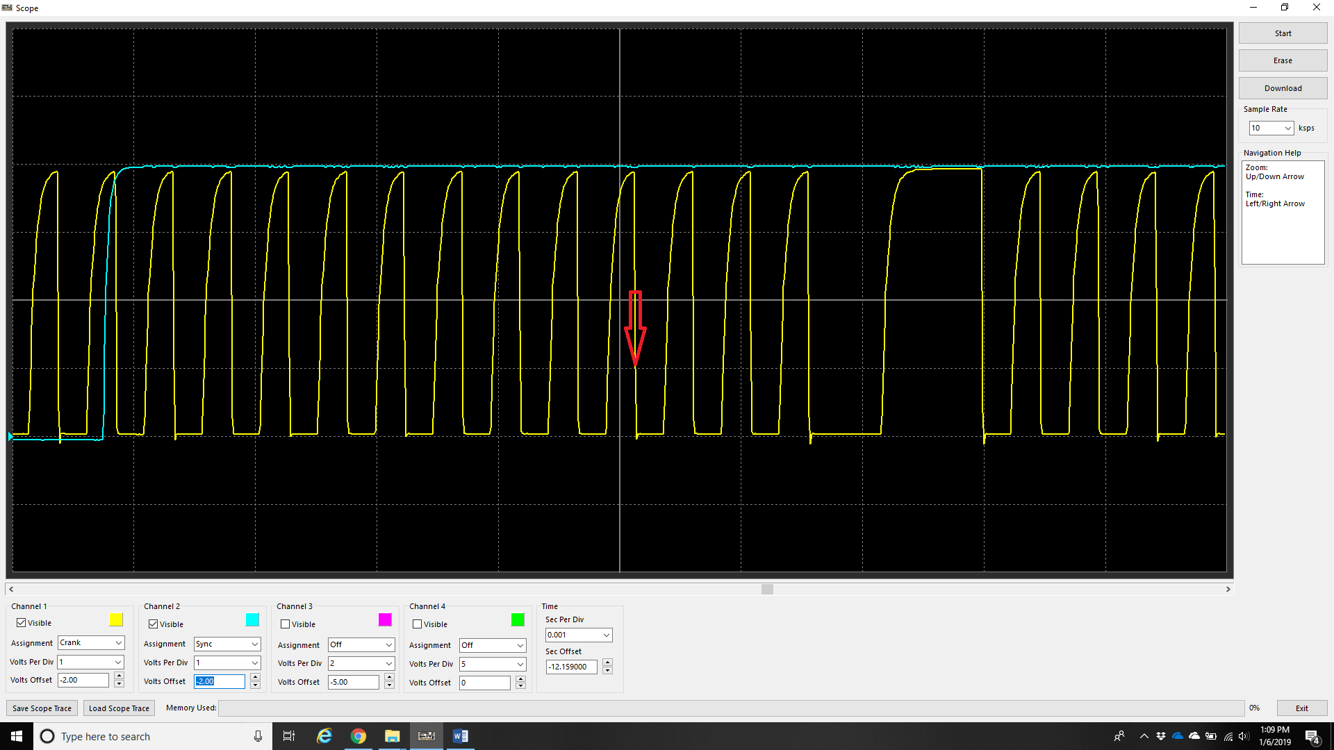
An example of a hall senor fast edge being the falling.
Triggering off the rising edge in either of the two above examples will cause the timing of the engine to wander at different RPMs.
Crank Sensor Pullup
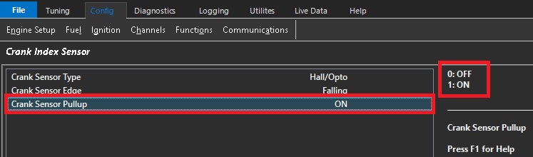
The numerical disable/enable input to control the 5volt pull-up available for Hall Effect, Optical & Proximity Crank sensors.
0: OFF
1: ON