Drive by Wire (DBW)
Drive By Wire (DBW) Application Guide
All KV Series and SL Series ECU’s support from 1 up to 4 independently controlled Drive by Wire (DBW) Systems. The DBW availability is ECU based and summarized below:
SL4 and SL8 – 1 motor
KV8 – 2 motor
KV12, KV16 (Rev2) – 4 motor
Select the control system and appropriate outputs from : Config View -> Function Setup -> Engine Functions -> DBW Control
Function Enable
OFF = Function is switched off and the selected output channels are deallocated.
ON = Function is switched on
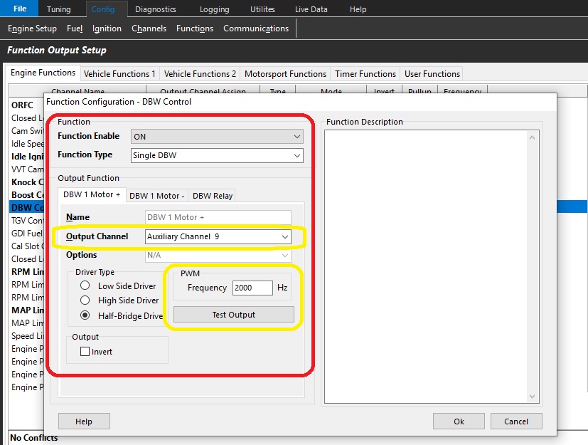
Function Type
4x DBW channels: (3 and 4 channels are only available on KV12/KV16 Serial Number > 1350)
- Single DBW - Using 2 Half-Bridge Drivers
- Dual DBW - Using 4 Half-Bridge Drivers
- 3 Channel - Using 6 Half-Bridge Drivers
- 4 Channel - Using 8 Half-Bridge Drivers
** See graphic above – Yellow
Output Channel Selection
There are dedicated paired outputs for each DBW channel.
DBW x Motor +ve (Positive) = Auxiliary 9 - 5A Continuous 8A Limit
DBW x Motor -ve (Negative) = Auxiliary 10 - 5A Continuous 8A Limit
OR
DBW x Motor +ve (Positive) = Auxiliary 11 - 5A Continuous 8A Limit
DBW x Motor -ve (Negative) = Auxiliary 12 - 5A Continuous 8A Limit
OR KV12 and KV16 Rev2
DBW x Motor +ve (Positive) = Auxiliary 13 - 10A Continuous 20A Limit
DBW x Motor -ve (Negative) = Auxiliary 14 - 10A Continuous 20A Limit
.
OR KV12 and KV16 Rev2
DBW x Motor + (Positive) = Auxiliary 15 - 10A Continuous 20A Limit
DBW x Motor - (Negative) = Auxiliary 16 - 10A Continuous 20A Limit
** See graphic above – Yellow
NOTE: DBW +ve (Positive) and DBW – ve (Negative) polarity is defined as fully opening the throttle plate when +12V and Ground is respectively applied to these pins.
Driver Type
Select “Half-Bridge Driver” in both the “DBW Motor +” and “DBW Motor – “ tabs.
Frequency
In most situations select 2000Hz. A range of 500Hz to 10kHz is available.
NOTE: Select the same frequency in both the DBW Motor + and DBW Motor – tabs for each respective motor.
DBW Relay
This relay will supply +12V to the ECU pin “Aux9-12 " (and/or Aux13-16) which will power the Half-Bridge drivers used to control the DBW Motor.
For safety reasons the DBW system will not operate until an Output Channel has been assigned.
When the ECU detects one of the following system errors the DBW relay will be switched off, shutting the DBW system down.
- Target Tracking Error
- Servo Position Tracking Error
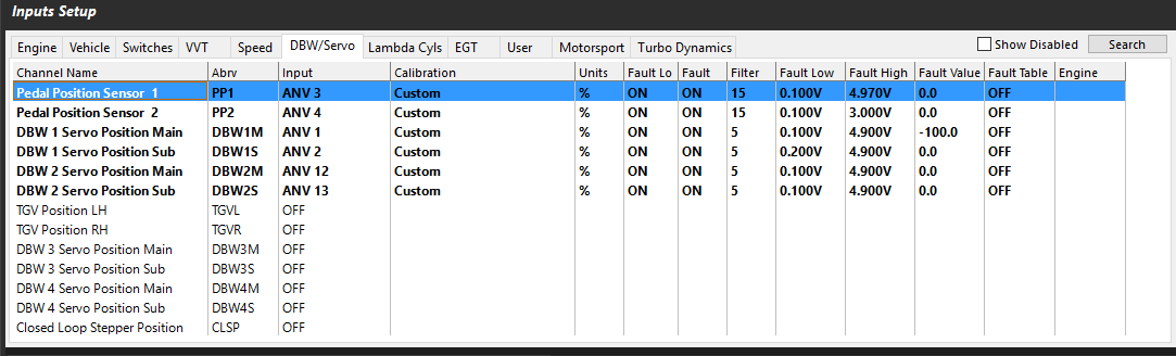
Input Servo Position Channels
For safety reasons, there are redundant inputs for pedal position and drive by wire servo position. Once the sensors are setup and calibrated, these positions are used to define the DBW target in closed loop.
There are pre-configured functions to help quickly calibrate the pedal position sensors, and throttle position sensors. See
Each DBW Channel has 2 dedicated inputs for Position Feedback. These are:
DBW 1 Channel Position Feedback
DBW 1 Servo Position Main = Analog Volt 1 - 16
DBW 1 Servo Position Sub = Analog Volt 1 – 16
*Or Maximum ANV channel count depending on ECU model
DBW 2 Channel Position Feedback
DBW 2 Servo Position Main = Analog Volt 1 - 16
DBW 2 Servo Position Sub = Analog Volt 1 – 16
DBW 3 Channel Position Feedback
DBW 3 Servo Position Main = Analog Volt 1 - 16
DBW 3 Servo Position Sub = Analog Volt 1 – 16
DBW 4 Channel Position Feedback
DBW 4 Servo Position Main = Analog Volt 1 - 16
DBW 4 Servo Position Sub = Analog Volt 1 – 16
Input Pedal Position Channels
Pedal Position 1 = Analog Volt 1 - 16
Pedal Position 2 = Analog Volt 1 - 16
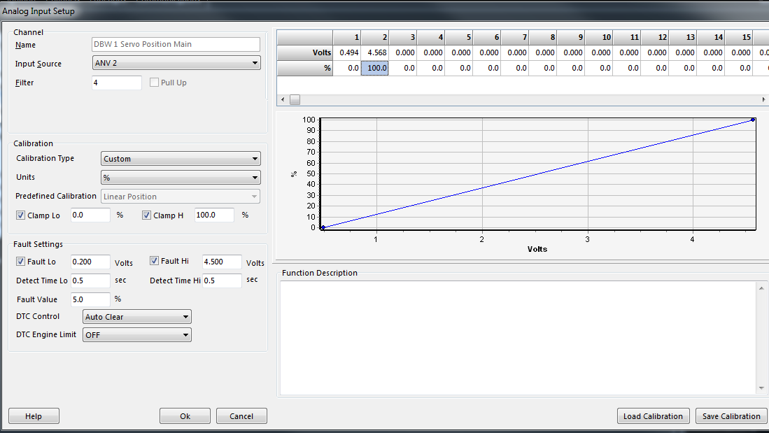
Sensor Calibration
The positioning sensors for the system must be calibrated like any other sensor. This can be done manually using the Calibration Table or there is an auto calibrate function described below.
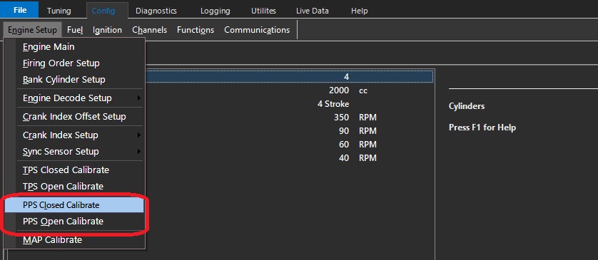
Auto Calibration of Pedal Sensors
See the following menu: Config View -> Engine Setup -> PPS closed and PPS open calibrate.
Throttle Position Input Channel
The Throttle Position Input channel is NOT required in DBW applications as the DBW uses Servo Positions Inputs; the Throttle Position Input channel can be switch OFF.
The ECU will automatically copy the DBW 1 Servo Position Main into the Throttle Position 1 runtime.
This will allow functions requiring this input (gauges, logging, ORFC, Lockouts) to continue working.