DBW Input Setup
Filter Settings
FIlter Setting Minimum = 0 (OFF)
FIlter Setting Maximum = 100
Recommended Filter Range = 2 - 5
Single DBW.
When using single DBW the following 4 inputs should be used. Although these inputs have no restrictions on their input assignment, the following is recommended.
DBW 1 Servo Position Main = Analog Volt 1
DBW 1 Servo Position Sub = Analog Volt 2
Pedal Position 1 = Analog Volt 13
Pedal Position 2 = Analog Volt 14
Dual DBW.
When using Dual DBW the following 6 inputs should be used. Although these inputs have no restrictions on their input assignment, the following is recommended.
DBW 1 Servo Position Main = Analog Volt 1
DBW 1 Servo Position Sub = Analog Volt 2
DBW 2 Servo Position Main = Analog Volt 3
DBW 2 Servo Position Sub = Analog Volt 4
Pedal Position 1 = Analog Volt 13
Pedal Position 2 = Analog Volt 14
DBW Pedal Position (PP) Calibration
Two options are available:
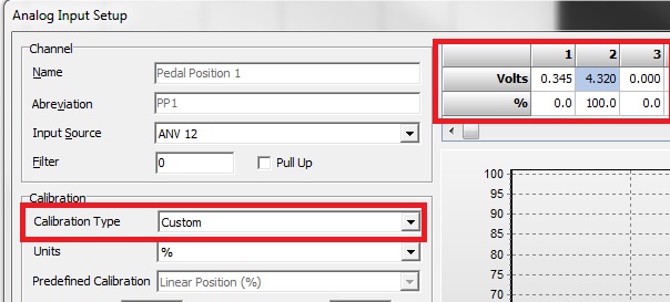
1) Manually enter in the Open and Closed voltages into each Calibration Table. Select Calibration Type to “Custom” and enter the value into the table as shown.
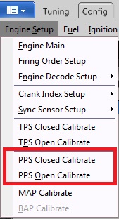
2) Automatic Calibration. Use the PP Closed/Open Calibration menu to automatically set these voltages. This can be access from Config View-> Engine Setup as shown.
When selected the PP1 and PP2 voltages will be written into their corresponding calibration tables. Make sure these channels have an Input Source set before selecting these menus.
These voltages can be viewed be going back to the Input Setup form as shown above.
 .
.