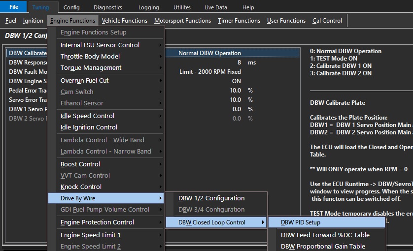
DBW Closed Loop Control - DBW PID Setup
DBW PID Setup
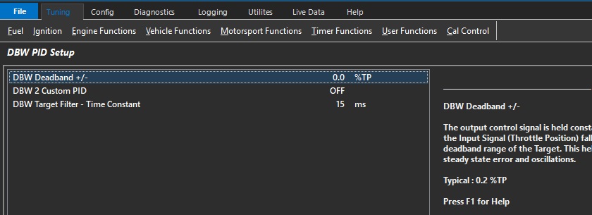
DBW Deadband +/-
The output control signal is held constant when the Input Signal (Throttle Position) falls within the deadband range of the Target.
This helps reduce steady state error and oscillations.
Typical : 0.2 %TP
DBW 2 Custom PID
If a second DBW servo is used that is of a different type, then the PID can be customized separately.
This enables configuration tables for DBW 2
** Most commonly used when a DBW servo is used for bypassing air for a turbocharged or supercharged vehicle (DBW Air Bleed)
0: OFF
1: ON
DBW Target Filter - Time Constant
Low pass digital filter Time Constant characterizes the speed taken to respond to a step input.
The value entered represents the time (in ms) it takes for the output to reach 63% of the stepped input value.
For example if the step input changed occurred from 0 - 50.0% and the Time Constant was 25ms, the filtered output would reach 31.5% after 25ms.
Tuning DBW PID
DBW servo position is controlled in the Torque Management section -> Pedal Demand.
See Torque Management – Throttle Mass Flow
See Torque Management – Pedal to Throttle Demand