DBW 1/2 Configuration
DBW 1/2 Configuration
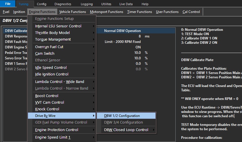
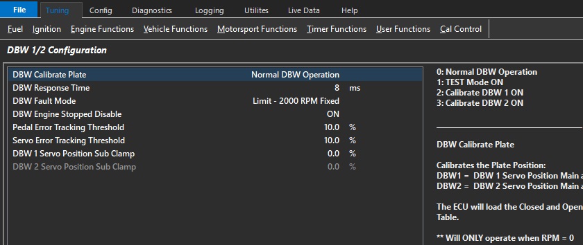
DBW Calibrate Plate
See the following menu: Tuning View-> Engine Functions -> Drive By Wire -> DBW 1/2 (or 3/4) Configuration
The following options are available:
0: Normal DBW Operation
1: TEST Mode ON
2: Calibrate DBW 1 ON
3: Calibrate DBW 2 ON
Modes 2 and 3 will calibrate the Plate Position (Servo Position):
The auto calibrate procedure populates the sensor calibration tables under input channels automatically for both fully closed and fully open positions.
NOTE:
** Will ONLY operate when RPM = 0
** TEST Mode temporarily disables the error checking allow final checks on the system to be performed
** Under no conditions should the vehicle be driven with the DBW system in TEST Mode.
** Calibrate Plate will not be possible where the Servo Position (Sub) reading clamps before complete blade deflection – Manual calibration will be required in this case.
Procedure for calibration:
1) Select which plate you need to calibrate (DBW1/2, or DBW 3/4)
Input pins for DBW Servo Positions must be enabled and setup correctly.
2) The ECU will move the throttle plate and calibrate the open and closed positions.
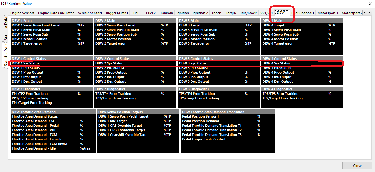
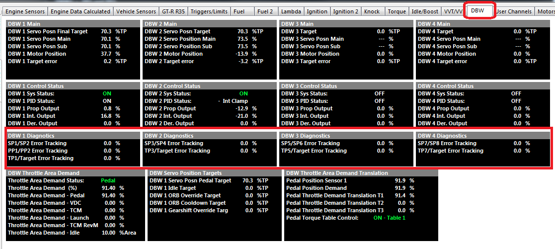
Use the ECU Runtime (F3) -> DBW/Sevro Tab -> DBW 1/2/3/4 - System Status window to view progress.
When the status reads “Calibrate Complete” , the DBW Calibrate Plate setting to can switched to “TEST Mode ON”.
This allows PID plate control but disables ALL tracking and safety features allowing PID calibration.
3) For PID control see Tuning View-> Engine Functions -> Drive By Wire -> DBW Closed Loop Control
Once the PID has been calibrated and the DBW Servo Position inputs are tracking correctly the TEST mode can be disabled.
4) Select DBW 1/2 Plate Calibration back to Normal mode.
DBW Response Time
The response time is the time from a commanded input change to the output changing.
Typical Time: 8 -12ms
DBW Fault mode
Emtron has an added layer of protection regarding a DBW fault (Servo position tracking, Target error, etc). The user can further define the engine behavior here.
DBW Fault Mode
0: Limit - 2000 RPM Fixed
1: Limp Home Table 1
2: Limp Home Table 2
In the case of a mechanically blocked throttle plate for example, even if the DBW system power supply is shut down, the engine could still run away.
This extra layer of protection allows the ECU to limit the engine RPM as well.
This makes a DBW system used with the Emtron product safer than even a cable operated system in regards to mechanical situation where a throttle is physically blocked open.Throttle Position Input Channel
The Throttle Position Input channel is NOT required in DBW applications as the DBW uses Servo Positions Inputs; the Throttle Position Input channel can be switch OFF.
The ECU will automatically copy the DBW 1 Servo Position Main into the Throttle Position 1 runtime. This will allow functions requiring this input (gauges, logging, ORFC, Lockouts) to continue working.
DBW Engine Stopped Disable
When the engine is stopped (RPM = 0 ) and Pedal Position is < 0.5% the DBW system can be disabled.
(Prevents battery drain with prolonged key-on use)
As soon as a Crank Signal is detected or the pedal moves > 0.5% the system becomes active again.
Pedal Error Tracking Threshold
When the difference between Pedal Position 1 and 2 is greater than the threshold, the ECU determines this to be an error condition and and increments a Error Counter.
The greater the difference, the faster the counter increments.
DBW Shutdown condition occurs when Error Counter reaches 100.
Typical 5.0%
Since the pedal position is validated by redundant inputs, once calibrated the position values can be compared and ultimately shutdown the DBW system if a sensor is failing.
The threshold here can be adjusted for the minimum amount of error needed for Error Tracking to start counting.
NOTE"
** Once “Error Tracking” for Pedal Position (PP) or Servo Position (SP) reaches 100%, the DBW system will be shut down and remain shutdown until the ECU power is cycled.
The Error Tracking rate is proportional to error so the bigger the error the faster the counter increments .
Servo Error Tracking Threshold
When the difference between DBW Servo Position Main and Sub is greater than the threshold, the ECU determines this to be an error condition and and increments a Error Counter.
The greater the difference, the faster the counter increments.
DBW Shutdown condition occurs when Error Counter reaches 100.
Typical 5.0%
DBW 1 Servo Position Sub Clamp
Used in applications when the DBW 1 Servo Position Sub signal does not span the full movement of the throttle plate.
Enter in the maximum %Servo Position as seen when the plate is fully open.
Typical applications include the Ford BA/BF/FG where this value is 51.0%
In normally applications set to 100% or
0 = OFF
DBW 2 Servo Position Sub Clamp
Used in applications when the DBW 2 Servo Position Sub signal does not span the full movement of the throttle plate.
Enter in the maximum %Servo Position as seen when the plate is fully open.
Typical applications include the Ford BA/BF/FG where this value is 51.0%
In normally applications set to 100% or
0 = OFF