DBW Torque Management
Introduction
The ECU uses a torque based system for DBW throttle plate control, which means all torque requests are done using Throttle Area, not Throttle Position.
There is no direct DBW Servo Position “Target” table, but instead a Throttle Area Demand table (more information below). So the throttle area directly relates to the engine torque which is why this function is under Torque Management.
For Engine torque calculations and during Torque limiting events the ECU converts the engines throttle area into engine airflow (g/s), then into engine torque (Nm) using mathematical models. This model allows the ECU to use this calculation in either direction:
- Throttle Area -> Airflow -> Engine Torque. Starting with throttle area the ECU can calculate the engine torque.
- Torque Target -> Airflow -> Throttle Area Target. Starting with a torque Target, the ECU can target a throttle plate area to achieve that torque.
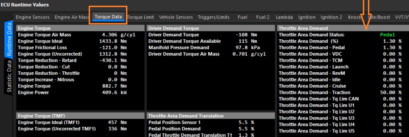
Throttle Area data is available either in the Runtime menu(F3) -> Torque or DBW 1/2 tab. The “Throttle Area Demand Status” indicates the current throttle area in use.
How does the ECU then convert throttle area to DBW servo position target?
This is done using the “Throttle Body Area Table " which translates Throttle Area into Servo Position. The ECU uses this as a lookup table, converting any requested Throttle Area into a Servo Position target for the DBW system. See the Throttle Body Area help topic for more information.
The process of converting Pedal Position -> Throttle Area Demand -> DBW Servo Target
To understand the process of converting Pedal Position into Throttle Area, carefully read this section.
- Make sure the Throttle Body setup is completed correctly. See DBW Calibration Guide.
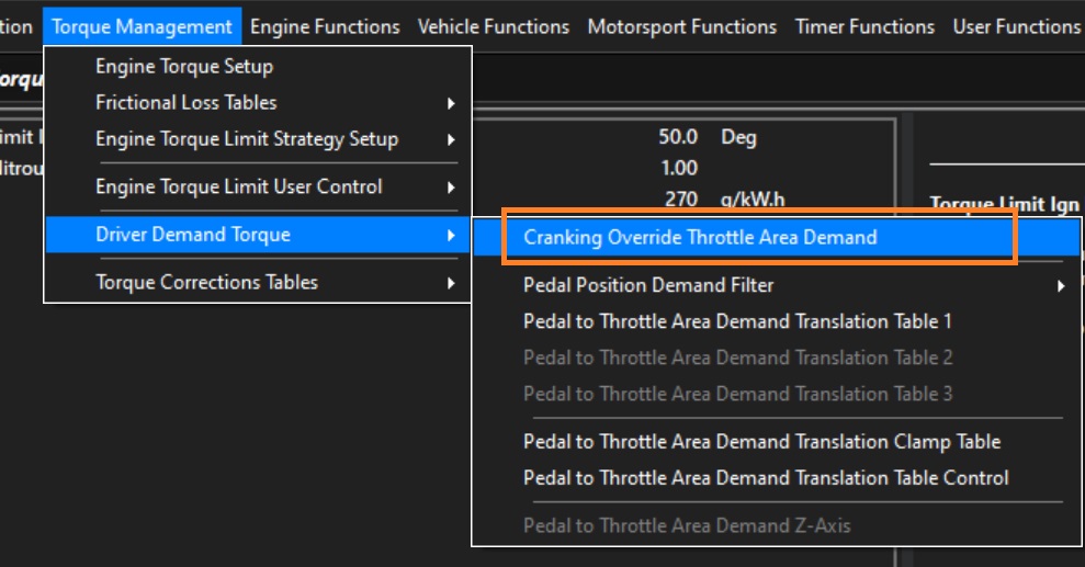
- Note the Throttle Cranking Area table. This ONLY gets applied during cranking and overrides any pedal request. See Cranking Throttle Area Demand
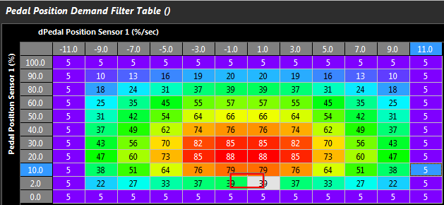
- The Pedal Position Sensor goes through a pedal position filter table to give you Pedal Position Demand . This will help smooth out signal fluctuations and improve the driving experience. Press H to read the help below the table. So this step is Pedal Position Sensor -> Pedal Position Demand
See the Pedal Demand Filter help topic for more information.

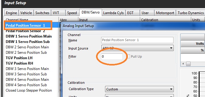
Tuning Tip: To avoid large input delays from the Pedal Position Sensor the filter setting on the raw input should be keep small . i.e the input filtering is done during the Pedal Position Sensor -> Pedal Position Demand so minimal filtering is required on the raw Pedal Position Sensor Input (See Config View -> Channels -> Inputs Setup -> DBW/Servo Tab). A Typical value will be between 0 - 4.
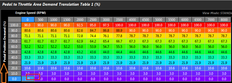
- The new Pedal Position Demand should be used to span the Pedal to Throttle Area Demand Translation Table 1. This demands a Throttle Area (not a position). This table controls the “feel”, making the engine feel more responsive or less responsive by controlling the Torque demand through Throttle Area.
So this step is Pedal Position Demand ->Throttle Area Demand
See the Pedal to Throttle Area Translation help topic for more information.
- In this last step the ECU will convert the Throttle Area Demand into the Servo Position Target for the DBW function. This is when the ECU uses the “Throttle Body Area” table mentioned at the start of this section. The ECU uses this as a “lookup” table to convert the Throttle Area Demand into a DBW Servo Position Target.
So this final step is Throttle Area Demand -> DBW Servo Position Target
See the Throttle Body Area help topic for more information and examples