Differential Control
Overview
The ECU can electronically control a Differential by modulating a solenoid at a fixed frequency and varying duty cycle.
The Differential Control and corresponding output duty cycle is determined by 3 different operating modes. A flow chart in the next section provides a visual overview of how the system works.
1) Handbrake. When this input is configured and the handbrake is ON the ECU applies 0%DC at its control output to unlock the diff. This overrides all other controls.
2) Throttle/Braking Select Table. This controls the selection of either the Throttle tables or Braking tables.
3) Braking Table. Used when the vehicle is under braking conditions.
4) Throttle Table. Used when the vehicle is under normal driving conditions.
Differential Control Status
The following Status information is available from the “Differential Output Status” runtime. This can be viewed from ECU runtime menu, under the Motorsport Tab.
0 = Function is OFF
1 = OFF - Output Channel not selected
2 = ON - Handbrake mode active
3 = ON - Throttle Tables active
4 = ON - Braking Tables active
Throttle/Braking Select Tables
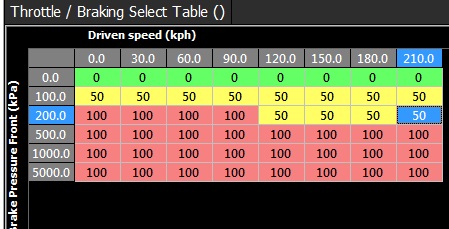
A 3D Table is used to select which Table controls the Duty Cycle to the Differential. This is either the Throttle Table(s) or Braking Table(s).
Table value 0 = Throttle Table(s)
Table value 100 = Braking Table(s)
Any other value = no change (hysteresis) . Normally use a value of 50 for this
There is no interpolation on this table.
This allows for a number of different strategies to control the switching between these two tables.
Examples:
1) Using Brake Pressure and Speed
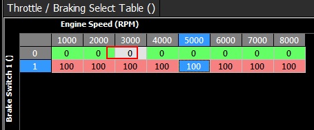
2) Using Brake Switch and Speed. 0 = Brake switch OFF, 1 = Brake Switch ON.
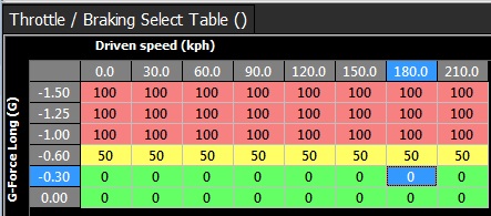
3) Using Longitudinal g-force from the ECUs internal accelerometer and Speed. A negative g-force is braking.
Braking Tables
When this mode is active 2 tables are used to generate the final Duty Cycle:
1) Main Braking Table
2) Braking Offset Table
Example:
Braking Table = 100%
Braking Offset Table = -10%
Final Duty Cycle = 100% -10% = 90 %DC
Throttle Tables
When this mode is active 3 tables are used to generate the final Duty Cycle:
1) MainThrottle Table
2) Throttle Offset Table
3) Steering Angle Offset Table
Example:
Throttle Table = 23%
Throttle Offset Table = -13%
Steering Angle Offset Table. = +8%
Final Duty Cycle = 23% -13% + 8 % = 18 %DC
Control Flow Chart
See this section for more information: Differential Control Flow Chart