EML-4 CAN Setup
EML-4 Setup.
Up the 3x EML-4 may be connected to the Emtron CAN bus. This allows the lambda data for up to 12 cylinders to be connected to the ECU. With the addition of every EML-4 module the CAN address for each data packet MUST use sequential addressing. The preferred addresses are listed below.
EML-4
- CAN Data Address = 65
- CAN Status Address = 66
EML-4
- CAN Data Address = 67
- CAN Status Address = 68
EML-4
- CAN Data Address = 69
- CAN Status Address = 70
ECU Setup.
ECU CAN Setup
- Select an available CAN node, CAN1 or CAN 2
- Select Baud Rate to 1Mbps
- Turn the selected CAN channel ON
- Select DATA Set = EML-4 (option 14)
- Select CAN Address = 65 (On a single installation this address MUST match the EML-4 CAN Data address. With multiply EML-4 modules connected to the BUS use the lowest address. The ECU CAN protocol in the mode uses sequential addressing and expects the received CAN address to get larger.
NOTE: All other CAN settings are not used.
ECU Input Setup
The Software allows each EML-4 sensor channel to be assigned to a cylinder.
- Select Input -> Input Pins Setup. Select the Lambda Cyls Tab
- Select the Lambda Cyl you want to config.
- Select the correct CAN Lambda Channel .In this example Cylinder 1 has been allocated to the LA 1 channel on the first EML-4 module.
The 1st EML-4 assigns LA1-4, the 2nd EML-4 assigns LA 5-8, the 3rd EML-4 LA 9-12.
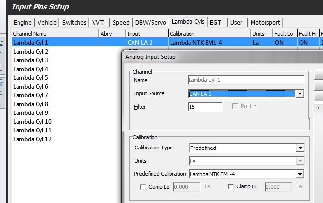
- Select Predefined Calibration to Lambda NTK EML-4. Don’t select Custom. Select Clamp Lo and Clamp Hi if required.
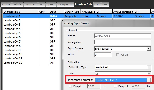
- The Fault Settings are not used from this form, as this operation if performed internally by the EML-4 are transferred to the ECU over CAN.
- The Engine Limit Table is still used.