Gear Shift Control
Gearshift Control Function Setup
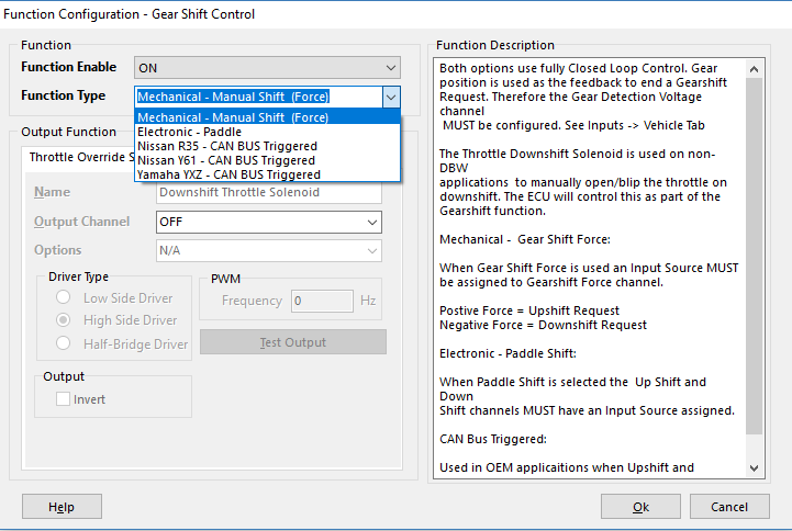
Emtron has multiple methods of Gearshift Control
- Config, Function Setup, Motorsport, Gearshift Control
Mechanical - Manual Shift (Force)
Electronic - Paddle
There are also other CAN BUS Triggered modes for Application Build versions.
** See those Application Build Manuals for details
- Configure Gear Position using the “Gear Detection Voltage” channel . This is normally a barrel position sensor located on the sequential gearbox. See Config View -> Inputs -> Vehicle Tab
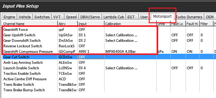
- Configure the Inputs. Configure the following from the Inputs -> Motorsport tab:
Paddle Shift mode
-
- Upshift Paddle Input
- Downshift Paddle Input
- Reverse Lockout Switch if required
- Compressor Pressure Input if required
In Force Shift mode
-
- Gearshift Force Input
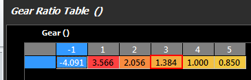
- For Paddle Shift to function correctly and safely at least least two(2) gear channel needs to be tracked for redundancy purposes. Commonly a Gear Detection voltage will be reported from a gear drum mounted to the transmission along with a speed sensor which may be used by the ECU to calculate the gear along with generating Engine Speed requests fro rev-matching limiters. The vehicles wheel diameter and final drive ratio should be confirmed correct. Then enter the correct transmission gear ratios into the table :
See Vehicle Dynamics->Vehicle Main The gear ratio table needs to be accurately set for this to occur.
. See Tuning view -> Vehicle Functions -> Vehicle Dynamics menu -> Transmission Gear Ratio table. Use -1 for Reverse.