Injector Channel Setup
Injector Channel Setup
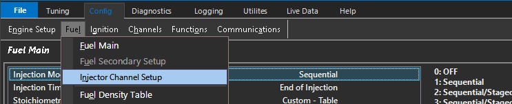
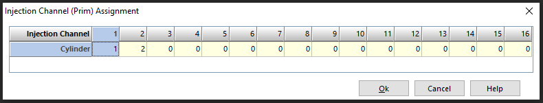
This tables assigns an Injection Channel to a Cylinder Number.
A 0 value indicates this channel is not used for Fueling and is therefore available for other functions.
Injection Mode = Sequential
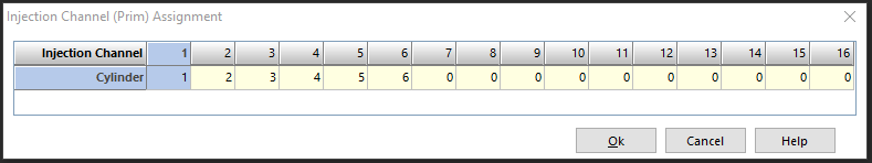
Example 1: KV12 ECU, 10 Cylinder application, 10 Sequential Injectors allocated on Injection Channels 1- 10
Injection Mode = Sequential/Staged Sequential
WARNING:
DO NOT use Fuel Engine Limiting when Staged Injection is enabled.
If there is an Injection Phasing difference between Primary and Secondary Injectors,
Cut synchronization is not always possible and may result in engine damage.
Ignition Liming is recommended.
Cylinder (Prim) = Enter the cylinder number for each channel connected to a primary injector
Cylinder (Sec) = Enter the cylinder number for each channel connected to a Secondary injector
Example 2: KV16 ECU, 8 Cylinder application, 8 Sequential Primary Injectors, 8 Sequential Secondary Injectors
Sequential Primary Injectors: Allocated on Injection Channels 1-8.
Sequential Secondary Injectors: Allocated on Injection Channels 9-16.
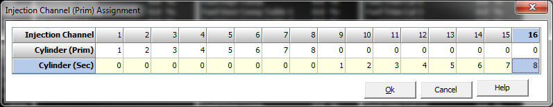
** Staging mode must have primary cylinders start with Cylinder 1
Injection Mode = Non Sequential
In this mode the odd injector channels are fired on one cycle, and even injector channels on the next. The ECU will calculate fuel mass required and divide it by the number of cylinders NOT the number of injector channels.
** Cylinder numbering, bank assignment, firing order is disregarded in this injection mode
Example 1:
6 injectors connected individually on a 6 cylinder engine
ECU will activate 1+3+5 on one TDC, 2+4+6 on the next (odd and even)
Example 2:
6 injectors connected individually on a 6 cylinder engine but ordered so the cylinders fire per bank
If the engine has dual banks (123 / 456), and the firing order is 1536242, the installer can re-order the cylinders vs injector outputs to synchronize firing per bank
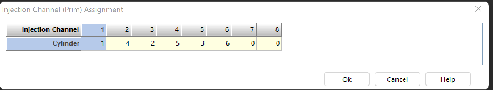
ECU will activate 1+3+5 on one TDC, 2+4+6 on the next (odd and even)
Injection Channels 123456
Cylinder Numbers 142536
This will fire 1+2+3 cylinders on one cycle, 4+5+6 on the next
8 injectors connected individually on a 8 cylinder engine but ordered so the cylinders fire per bank
If the engine has dual banks (1357 / 2468), and the firing order is 18436572, the installer can re-order the cylinders vs injector outputs to synchronize firing per bank
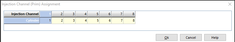
ECU will activate 1+3+5+7 on one TDC, 2+4+6+8 on the next (odd and even)
Injection Channels 12345678
Cylinder Numbers 12345678
If the engine has dual banks (1234 / 5678), and the firing order is 15486372, the installer can re-order the cylinders vs injector outputs to synchronize firing per bank
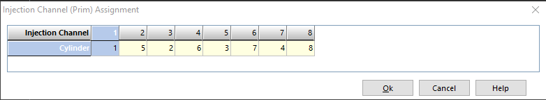
ECU will activate 1+3+5+7 on one TDC, 2+4+6+8 on the next (odd and even)
Injection Channels 12345678
Cylinder Numbers 15263748
ECU will activate 1+2+3+4 on one TDC, 5+6+7+8 on the next (odd and even)
Example 3:
2 injectors connected with 3 injectors paired to each output on a 6 cylinder engine
Engine will fire output 1 on one TDC, 2 on the next
The installer can group the cylinders they want to fire on each cycle
** This method will NOT provide the best injector deadtime and linearization control.
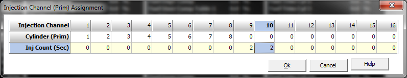
Injection Mode = Sequential/Staged Group
WARNING:
DO NOT use Fuel Engine Limiting when Staged Injection is enabled.
If there is an Injection Phasing difference between Primary and Secondary Injectors,
Cut synchronization is not always possible and may result in engine damage.
Ignition Liming is recommended.
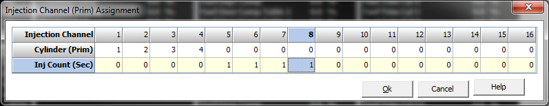
In this mode the Primary Injectors are sequential and the Secondary Injectors are Group/Non sequential. The Secondary Injectors are opened once per engine cycle. The Secondary Odd and Even Injection channels are run anti-phase. The Injectors on Even Channels are started at 0.0 Degrees BTDC. The Injectors on Odd Channels are started at 360.0 Degrees BTDC
Cylinder (Prim) = Enter the cylinder number for each Injection Channel connected to a primary injector
Inj Count (Sec) = Enter the number of secondary injectors connected to an Injection Channel. This is group staged and is NOT referenced to cylinders.
Example 3:
Sequential Primary Injectors: Allocated on Injection Channels 1-4.
Grouped Secondary Injectors: One injector on each Injection Channel 5,6,7,8
Example 4:
Sequential Primary Injectors: Allocated on Injection Channels 1-8.
Grouped Secondary Injectors: Two injectors on each Injection Channel 9,10.