Input Setup
Input Setup
There are two main groups of Input Setup Type - Analog Inputs and Digital Inputs. They are grouped into to standard form types, that are mostly the same for all inputs.
Analog Inputs
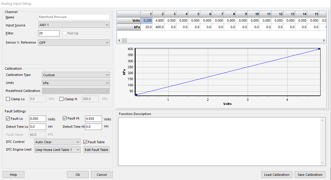
Above example shows Manifold Pressure Sensor channel.
Input Source
Choose your input source.
** See ECU Hardware Specifications for assigning the best source for your input channel
Filter
Each input can have its own moving average filter applied.
Pull Up
If the channel has pull up capability, the pull up flag will be available.
Sensor V. Reference
Select number of Analog Inputs have Ratio Metric input functions. Select the 5V V Reference Pin if applicable.
** See Ratio Metric Reference Manual available online
Calibration Type
Customize - via Multii-point table on the right
Pre-defined - Via dropdown list (Predefined Calibration)
Clamp Lo/H
Clamp the Low/High value of the input
Fault Lo/Hi
Set Low/High fault voltages
Detect Time Lo/Hi
Set Low/High detect time for fault values to be effective
Fault Value
Set the substitute value for each individual input when Fault is active
DTC Control
Set DTC (diagnostic trouble code) behavior
Auto Clear
Manual Clear (ECU must be connected to clear fault codes)
DTC Engine Limit
Set the Limp Home Limit Table to be used if DTC is active
Limp Home Table 1
Limp Home Table 2
Off
Fault Table
Some major sensor inputs (MAP, TPS, etc) have the ability to enable “Fault Table”, where in fault mode, substitute values can be more than one value.
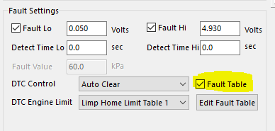
When enabling Fault Table, Fault Value becomes inactive. Clicking Edit Fault Table gives the user a larger table to add more than one value for substitute values
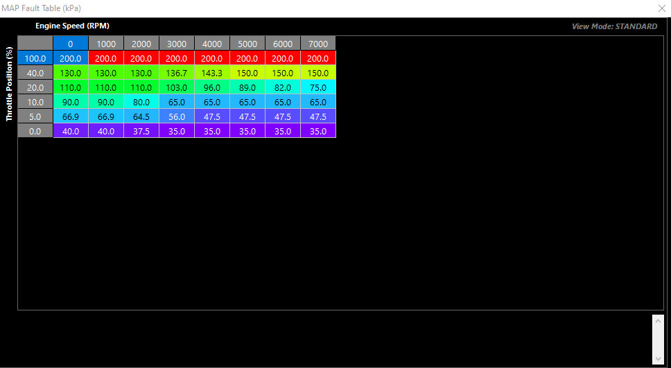
Axis for table is open, and as an example you can see for MAP substitute values, the axis is selected to look at TPS vs RPM
Digital Inputs
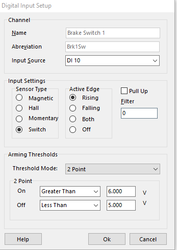
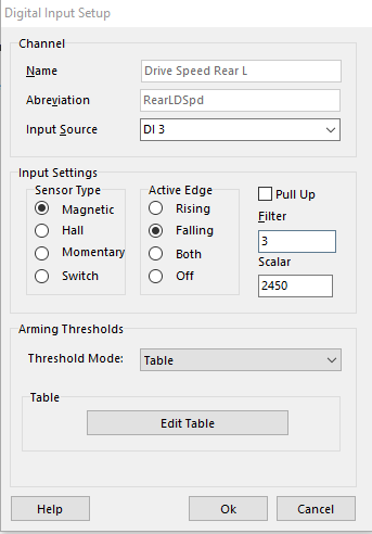
Above examples show a Brake Switch Input and wheel speed input
Input Source
Choose your input source.
** See ECU Hardware Specifications for assigning the best source for your input channel
Sensor Type
Select the Sensor Type
Magnetic
Hall
Momentary
Status will “latch” whenever the thresholds are satisfied
Switch
Will be active when the thresholds are satisfied
Active Edge
Rising
Falling
Both
Off
Pull Up
If the channel has pull up capability, the pull up flag will be available.
Filter
Filter value
Threshold Mode
2 Point
** Only to be used for switch inputs
Table
Table value dictates voltage crossover where signal is valid (voltage level must be higher than this arming voltage)
Used for frequency inputs
Active Edge must be configured correctly
See ECU Hardware Specifications for inputs with configurable table arming thresholds
2 Point On/Off
Voltages in which 2 Point mode thresholds are active
Hardware Specifications
Analog Inputs 1- 14
- Input Analog Voltage Range: 0 - 5.0V
- 12 Bit ADC (4096 points)
- 1st order 100Hz Low pass filter.
- 1.22 mV (0.0122V) resolution.
DI 1- 8
- Input Analog Voltage Range: 0 - 20.0V
- 4.88mV resolution (10 bit effective resolution using 20V Range - 1024 points)
- Maximum usable analog input voltage: 20.0V
.
DI 9- 14
- Input Analog Voltage Range: 0 - 20.0V
- 19.5 mV resolution (10 bit effective resolution using 20V Range) - 256 points
- Maximum usable Analog Input Voltage: 20.0V
Example A. Take MAP sensor 0 - 5V input into the ECU with range of 0.0 kPa to 400.0 kPa (3 bar of boost)
a) Using AN 1- 14 (12 Bit resolution)
MAP Resolution = 400 kPa / 4096 = 0.097 kPa. This means the ECU can measure the pressure actuate to within 0.097 kPa using a 4Bar Map sensor.
b) Using DI 1- 8 (10 Bit resolution)
MAP Resolution = 400 kPa / 1024 = 0.488 kPa. This means the ECU can measure the pressure actuate to within 0.488 kPa using a 4Bar Map sensor.
c) Using DI 9- 14 (8 Bit resolution)
MAP Resolution = 400 kPa / 256 = 1.56 kPa. This means the ECU can measure the pressure actuate to within 1.56 kPa using a 4Bar Map sensor.
Example B. Take EGT 0- 5V input into the ECU with range of 0.0 DegC to 1000.0 DegC
a) Using AN 1- 14 (12 Bit resolution)
EGT Temperature Resolution = 1000 degC / 4096 = 0.24 degrees. This means the ECU can measure the EGT temperature actuate to within 0.24 degrees
b) Using DI 1- 8 (10 Bit resolution)
EGT Temperature Resolution = 1000 degC / 1024 = 0.98 degrees. This means the ECU can measure the EGT temperature actuate to within 0.98 degrees or 1.0 degrees rounded up.
c) Using DI 9- 14 (8 Bit resolution)
EGT Temperature Resolution = 1000 degC / 256 = 3.90 degrees. This means the ECU can measure the EGT temperature actuate to within 3.90 degrees or 4.0 degrees rounded up.
NOTE: The Digital Input voltage channels are normally used to read switch inputs and for ECU self testing procedures. However, DI1-8 channels still has very good resolution at 10 Bit with a 0 - 20V range so pressure and temperature sensors can still use connected to these channels.