Launch Control (Nm) Setup
Launch Control (Nm)
Entry Range
Controls when the Launch Torque Limit function will turn ON.
The Launch Torque Limit and PID control will switch ON when the RPM enters set range of the Launch RPM Target.
This is a negative engine speed value that sets the range below the Launch RPM Target
Once ON it will latch and remain ON until the system exits to standby mode
Exit of the Launch control is user defined in Launch Disarming
Example:
Launch RPM Target = 4000
Entry Range = -200
Rpm < 3800 Launch Control Torque Limit is OFF
Rpm >= 3800 Launch Control Torque Limit is ON
Torque Target Margin
This setting is used to increase/decrease the Engine Torque Target once the engine is within the Entry Range of the Launch RPM Target.
The margin is added to the Launch Torque target on entry and decays to the Launch Torque Target at a linear rate as the engine approaches the Launch RPM Target.

Tuning Tip:
Use 0Nm initially as a starting point. This setting is used to control the entry behavior.
** If the engine is struggling to reach Launch Target, Increase Margin
Example:
Launch RPM Target = 3000 RPM
Entry Range = -200 RPM
Launch Torque Target = 10 Nm
Launch Torque Target Margin = 100Nm
RPM < (Launch RPM Target - Entry Range ) the Torque Limit is OFF
RPM > (Launch RPM Target - Entry Range) the Torque Limit is latched ON
Rpm < 2800. Torque Limit OFF
Rpm = 2800. Torque Target = 10Nm + 100Nm = 110Nm
Rpm = 2850. Torque Target = 10Nm + 75Nm = 85Nm
Rpm = 2900. Torque Target = 10Nm + 50Nm = 60Nm
Rpm = 2950. Torque Target = 10Nm + 25Nm = 35Nm
Rpm = 3000. Torque Target = 10Nm + 0Nm = 10Nm
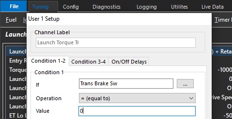
Launch Torque Transfer User Channel
Allows the User to control when the Torque Target transitions from “Static Torque Target” table to the “Launch Moving Torque Target”
** This User MUST be set up or Launch Control will not enable
Example:
Trans Brake Switch Status could be used as a user channel input to trigger the transition from Launch Torque Target to Launch Moving Torque Target
Launch Static Mode Speed Lockout
When the speed input is greater than this value, the Launch System will lockout the “Static Torque Target" and maintain the “Moving Torque Target". This prevents the accidental return of the launch system back into Static Mode.
** NOTE: Make sure the “Launch Speed Reference Channel” is set correctly **
Typical Value = 10 kph
Launch Speed Reference Channel
Defines the speed channel used to Disarm/Arm the Launch Control System.
0: OFF
1: Drive Speed
2: Ground Speed
3: Drive Speed Front L
4: Drive Speed Front R
5: Drive Speed Rear L
6: Drive Speed Rear R
7: Undriven Speed Front L
8: Undriven Speed Front R
9: Undriven Speed Rear L
10: Undriven Speed Rear R
11: Front Axle Speed
12: Rear Axle Speed
13: Vehicle Speed
14: Engine Speed
15: Input Shaft Speed
16: Output Shaft Speed
17: GPS Speed
Launch Enable Switch Lockout
When set to ON the Launch Switch can be used to activate the Launch Control System.
0: OFF
1: ON
ET Lo Lockout
This is an under-temperature lockout. The Launch Control system will be ready for arming when the Engine Temperature is greater than this value.
For the Launch System to be ready for arming the following must be true:
Throttle/Pedal > Launch TP/PP Lockout setting AND
Engine Temperature > ET Lo Lockout setting AND
Engine Temperature < ET Hi Lockout setting AND
User Lockout = ON (if enabled)
ET Hi Lockout
This is an over-temperature lockout. The Launch Control system will be ready for arming when the Engine Temperature is less than this value.
For the Launch System to be ready for arming the following must be true:
Throttle/Pedal > Launch TP/PP Lockout setting AND
Engine Temperature > ET Lockout setting AND
User Lockout = ON (if enabled)
Launch User Lockout
The Launch Control system will be ready for arming when the User Channel (if assigned) is ON.
For the Launch System to be ready for arming the following must be true:
Throttle/Pedal > Launch TP/PP Lockout setting AND
Engine Temperature > ET Lockout setting AND
User Lockout = ON (if enabled)
0: OFF
1: User Output Channel 1
2: User Output Channel 2
3: User Output Channel 3
4: User Output Channel 4
5: User Output Channel 5
6: User Output Channel 6
7: User Output Channel 7
8: User Output Channel 8
9: User Output Channel 9
10: User Output Channel 10