Multi Tooth Setup
Multi Tooth Setup
This allows the user to define a Custom decoding mode for the ECU to use. In order for the ECU to synchronize timing of the engine, an “index tooth” position must be identified. :
The following settings are configured in this menu item :
Crank Tooth Count. See Crank Tooth Count for more information.
Missing Tooth Count. See Missing Tooth Count for more information.
Crank Index Position. See Crank Index Position for more information.
Sync Position Sensor. See Sync Sensor Position for more information.
Gap Detection Method. SeeGap Detection Method for more information.
When using a Custom Decoding mode, it is important to understand how and where the “index tooth” is identified, especially if the engine has adjustable triggers (mechanically).
On Non-Missing tooth Crank Triggers, there must be a sync sensor so the ECU can identify the “Index Tooth”
The Sync Sensor must be Camshaft driven if sequential fuel injection/direct fire ignition modes are being used
Missing Tooth Triggers do not require a sync sensor to identify the “Index Tooth”
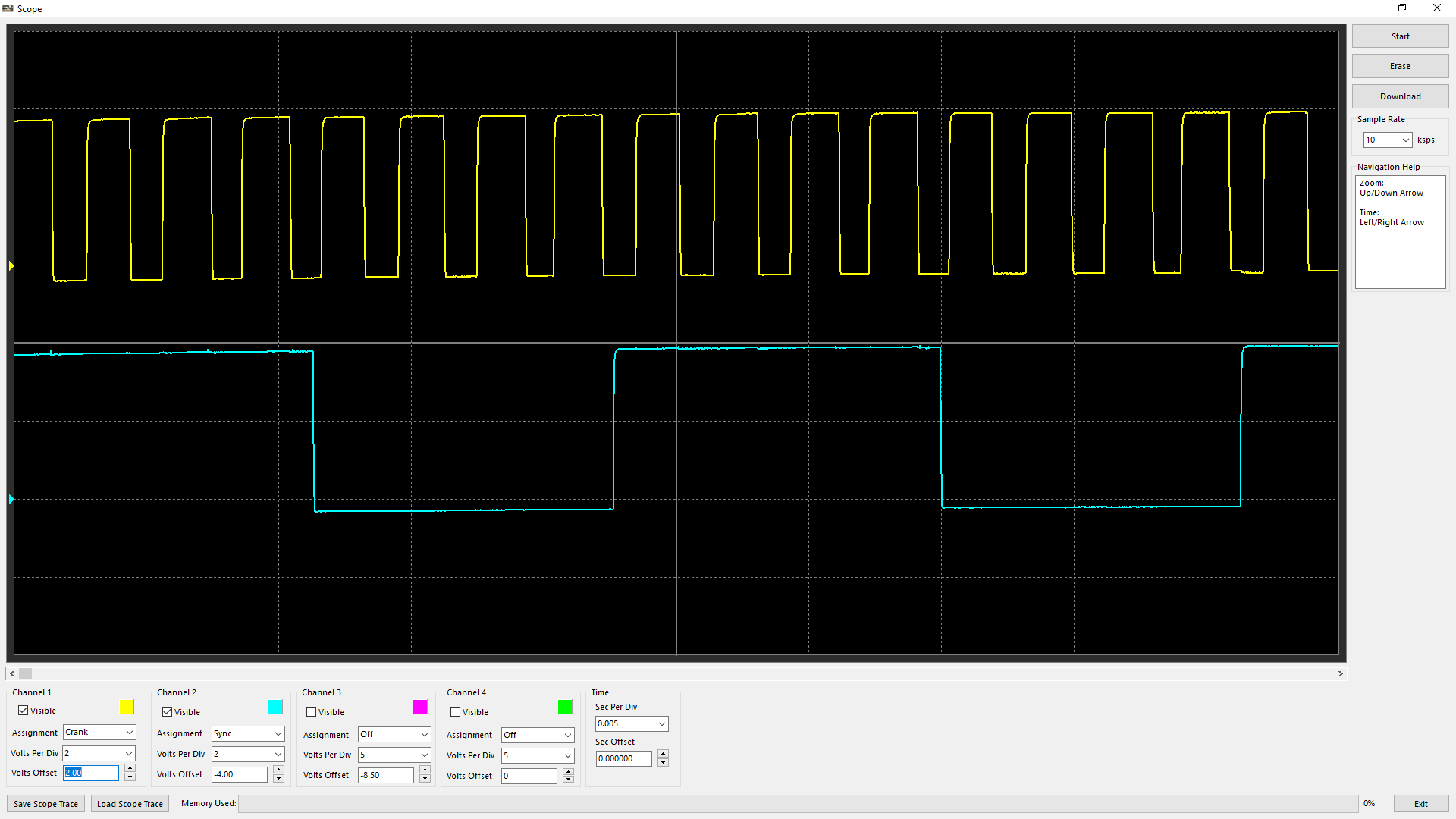
An example of a 4 Tooth Crank Wheel with a single tooth (50/50) Sync Sensor driven off a Camshaft (both Hall sensors)
Also known as 1-Tooth per TDC
** Note - This trigger could also be an example of a Crank Trigger being driven off of a Distributor (8 teeth), and therefore Camshaft driven
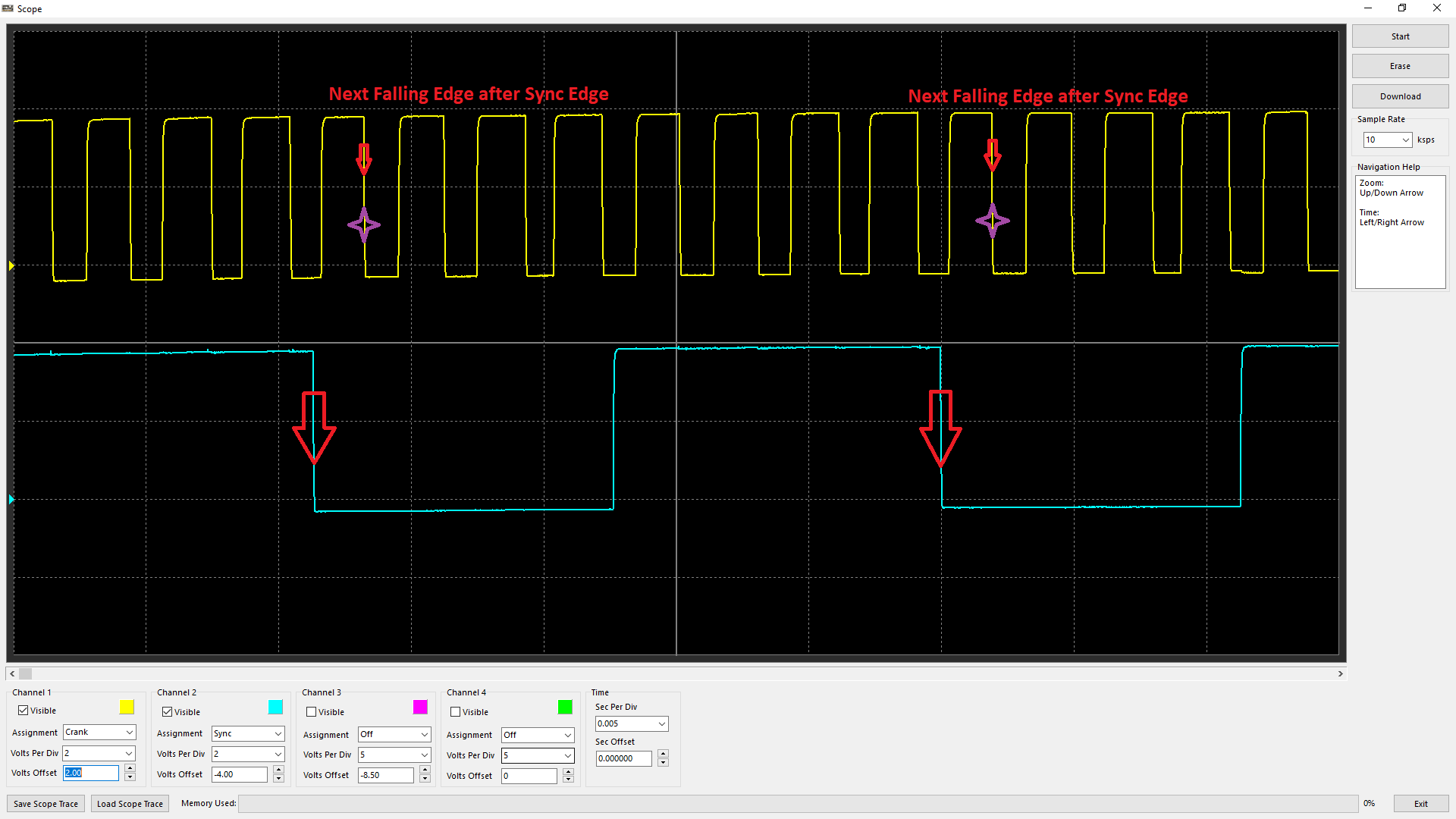
In this case, Edge configuration being set to both Falling Edge (see Crank Index/Sync Sensor Setup), the “Index Tooth” is identified as above
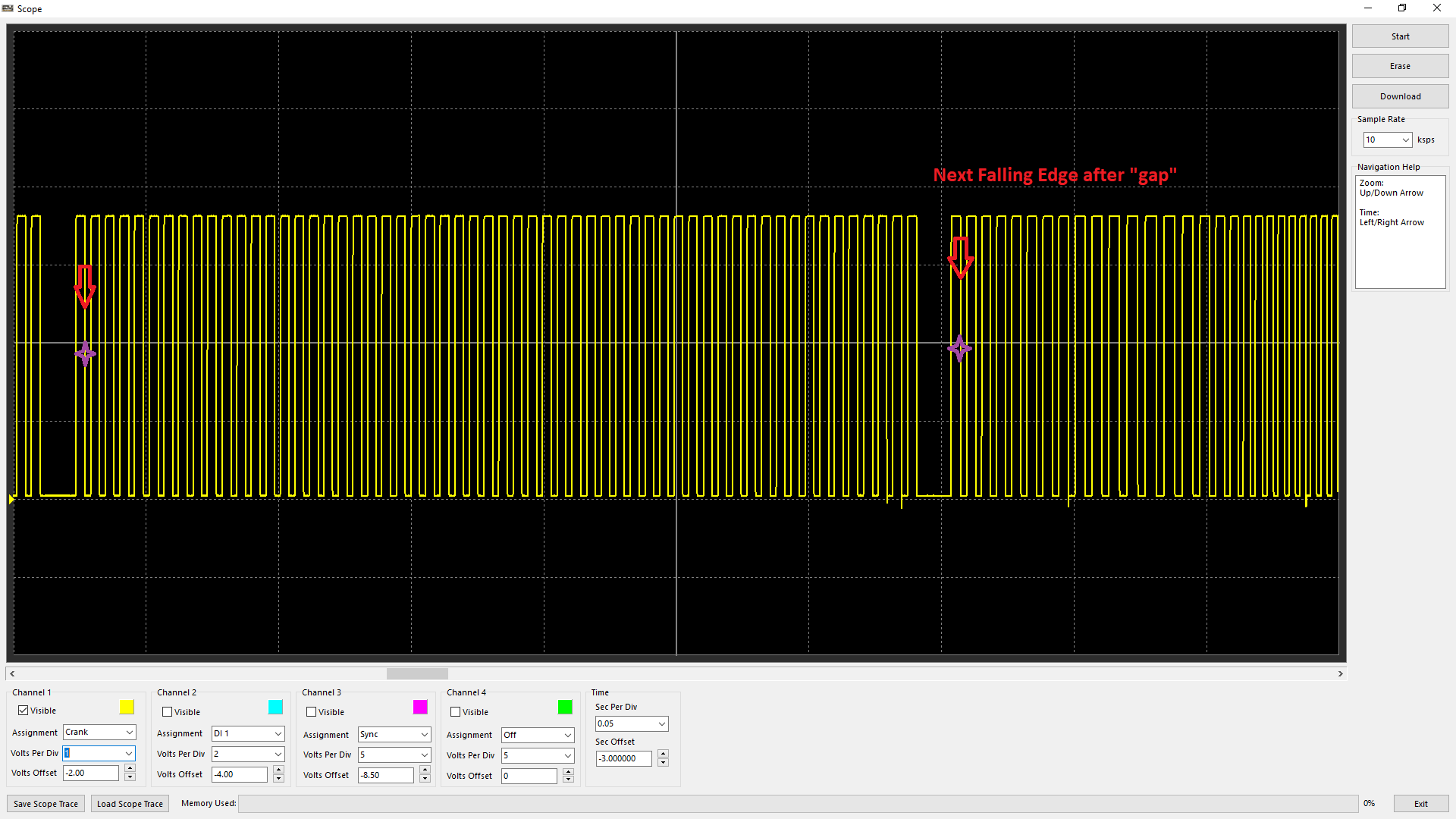
With a Missing Tooth crank trigger, the “Index Tooth” is recognized by the next Falling Edge after the gap position.
** Note - no Sync Sensor is even shown
** When using Magnetic Triggers, with incorrect polarity the ECU will not be able to recognize the gap and/or the “Index Tooth” position correctly. See Scope - Uses of Scope - Improper Crank/Sync Sensor Polarity
Sync Position %
Sync position refers to the point in which the ECU is identifying the Sync Edge location. This reference point can be critical as if there is any discrepancy to this position mechanically (wandering between the crank and cam trigger due to slack in cam belt/chain), it can cause crank/sync errors, engine cycle change, or even the firing order to change (especially in the case of non-missing crank trigger setup).
Emtron calculates the following channel for monitoring, diagnosis, and logging purposes - Sync Position %
The Sync Position % is calculated by factoring the position of the Sync Edge between consecutive Crank Teeth.
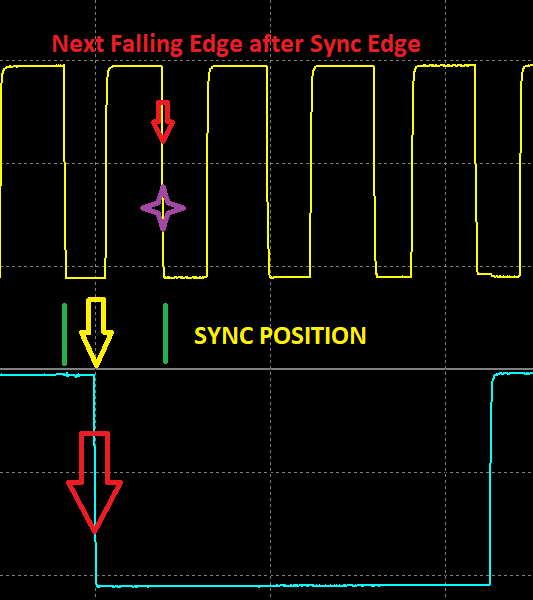
Looking at falling edges, the distance between crank teeth can be identified by the green lines, and the sync edge is identified by the yellow arrow. The value would be Sync Position % - 33% approximately in this case.
Best practice is to aim for a Sync Position % - 50%.
** Note - The higher the crank tooth count, the less resolution this runtime generally will have. IE a 60-2 trigger will have a much more unstable Sync Position % value vs a 1-Tooth Per TDC