Basic Configuration
Basic Configuration
Software Navigation
From the Welcome Screen, selecting Open File, or Open ECU (ECU Detected is required) the calibration file will be opened.
From here, you can navigate through a number of menus, tabs, sub tabs, etc.
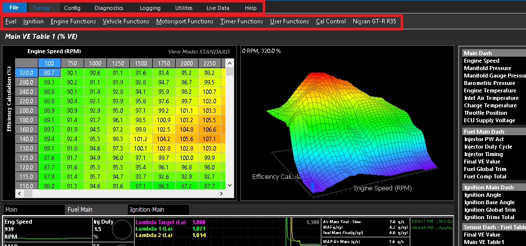
For configuration, clicking the config tab at the top is where to start.
The Emtune software has a very systematical approach to configuration.
Start on the left side “Engine Setup”, and work your way over from left to right.
Do not skip sections. Following this practice as accurately as possible will ensure tuning process will move smoothly in the future.
WARNING: Improper entry in any part of the setup could be detrimental to the electronics AND the hardware!
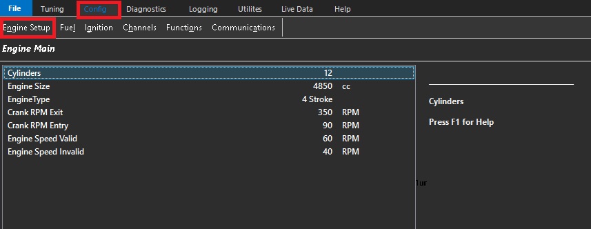
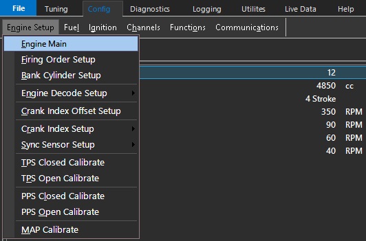
Engine Setup
\
Setup each tab from top to bottom. See help file for explanation of each individual function, as well as help text in the respective configuration screens.
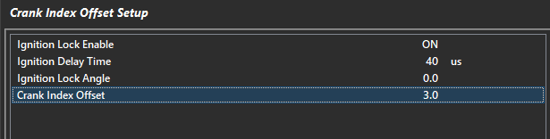
Crank Index Offset Setup
This section synchronizes the engine timing.
**Crank index offset MUST always be checked regardless of trigger pre-configuration.
1) Always check crank index position at ignition lock angle 0.0 (especially when running waste spark).
2) Ignition delay time should be validated at this time and adjusted.
3) As RPM is increased, timing should stay at the ignition lock angle.
If this does not occur - Adjust the ignition delay time until this is achieved.
Quick Calibrations
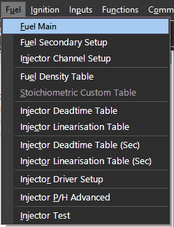
Fuel
Define all your fuel setting under the Fuel heading.
Fuel Flow Rate/Ref Injector Size
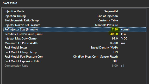
The Ref Injector Size flow rate must match the Ref Static Fuel Pressure value
The Ref Static Pressure Value is pressure value that differential/relative fuel pressure at the injector for this injector flow rate value.
** If Fuel Model: Fuel Pressure Corr. Is “On (Fuel Press Corr – Sensor Fitted)”, then this Ref Static Fuel Pressure value is used as the base Fuel Pressure Differential.
The following runtimes will be generated from this information:
Fuel Pressure Diff – This is the effective pressure at the injector
Fuel Pressure Diff Offset – This is the deviation from the differential pressure target (or the reference static pressure entered commonly
Fuel Model Pressure Correction – The percentage of compensation added/subtracted based on differential pressure offset
** If Secondary Injection is used, Fuel Pressure 2 channel MUST be used, and all runtimes above (2) are available and act independently.
These channels can be used all over the ECU calibration, for compensation for deadtime, engine protection, etc.
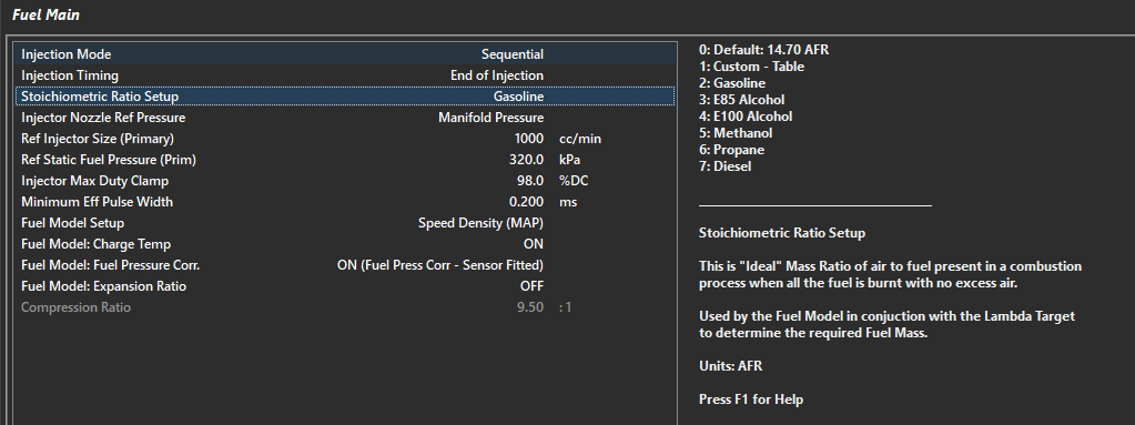
Stoichiometric Ratio Setup
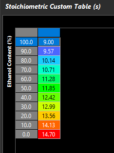
The airflow model will determine air mass flowing through engine a number of ways, then reference the stoich setup to determine how the “Lambda Target” table quantifies the fuel mass needed in the model. There are a number of pre-defined fuel types to choose from, but also a “Custom - Table” selection for pump fuel with ethanol, flex fuel vehicles, etc. See the ECU sample file (Custom - Table), or build your own table if using a odd fuel.
** Not having the correct Stoich Ratio will bake large error into the entire model and compensations
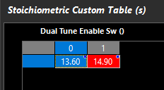
Above is showing how two fuel types can be used with different Stoich values with a “Dual Tune Enable Sw”
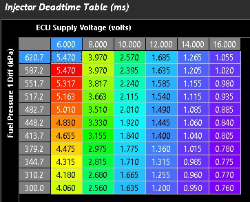
Injector Deadtime and Linearsation
It is very important to have your Injector Size (cc/min) as accurate as possible, as well as the Ref Static Fuel Pressure.
If using any fuel pressure compensation in the model (which you can turn on and off), the Ref Static Pressure is what is used to compensate injection quantity vs effective fuel pressure (differential fuel pressure).
There are 3D table functions for Fuel Density, Custom Stoichiometric (commonly used for flex fuel function), Deadtime, and Linearizion.
** Injector deadtime accuracy is critical.**
Correct deadtimes ensure the proper amount of pulse width is added to the effective pulse width (as calculated by the fuel model).
Improper time entry usually results in exaggerating VE entries, especially in engine load ranges when the pulse width is small.
It should be taken into consideration that effective fuel pressure affects injector deadtime, so using injectors with good data sheets is the best idea. Most good injectors have a latency multiplier vs fuel pressure, or a complete table available.
These values should be translated and entered into the tables as accurately as possible.

Tuning Tip:
Injector Dead times can be validated using the Emtune Software by using the Wideband Lambda control. If you add 10% to your VE table (@ 3000rpm / 80kpa load for example), you should see a corresponding negative 10% trim applied via the Wideband lambda control. If you don’t, then you know your dead times need some attention.
By utilizing a dead time table available in your Emtune software that is close. The correct dead time for your injector can be quickly arrived at by simply globally moving the table up & down. The voltage slop of the dead times can be further validated by removing the alternator charge and allowing the supply voltage to drop away. Correct dead times allow the engine to operate correctly over a wide range of variable conditions
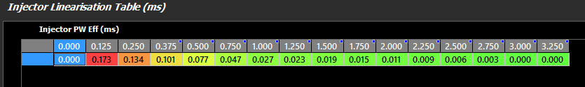
** Injector Linearization is considered a raw pulse width correction factor to correct the fuel flow at different pulse widths
(generally more sensitive at low pulse widths). These numbers can be positive or negative.
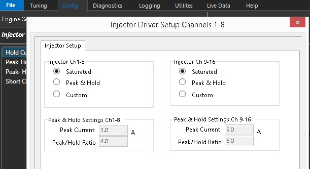
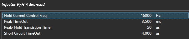
There is a full configuration function for peak and hold injection where you can define the injector type (saturated vs peak and hold), and define opening and hold currents.
The injector test function also allows you to pulse each injector anytime the engine is off.
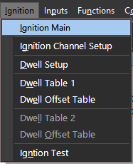
Ignition
Define all your ignition setting under the Ignition heading.
**Ignition firing edge synchronizes the calculated ignition timing with the physically ignition system itself.
In most cases where the ignition system has ECU controlled dwell (following the dwell table entry), the firing edge will be falling as this is when the coil will inductively transfer spark energy to the spark plug.
Mapped dwell time affects coil charge before this event.
Ignition systems that require the opposite signal (dwell period reversed) generally have a rising firing edge.
Ignition systems that control their own dwell period separately also generally require rising firing edge.
Ignition Timing should be validated with a timing light ALWAYS.
A good test for correct firing edge configuration is to change the dwell time and observe the ignition timing does not change.
Improper set up here can cause false ignition timing, weak spark and even DAMAGE to the ECU or the vehicle Ignition system.
Each cylinder can be assigned two different dwell tables. Each dwell table can be offset by a secondary table as well.
The ignition test function also allows you to pulse each injector anytime the engine is off.
Inputs
This comprehensive setup will specify all Inputs to the Emtron ECU system.
It has a tab structure which has a similar function to the configuration setup.
Input Pins
Inputs can be configured using select analog and digital inputs.
The hardware configuration for different ECU types is listed below.
SL Series ECU –
ANV 1-10 12 bit resolution 0-5v analog voltage inputs
ANV 7-10 have switchable pull up to 5v through 1k ohm (temperature)
DI 1-8 0-30khz input frequency range with switchable pull up to 9v through 4.7k ohms
DI 1-8 10 bit resolution 0-20v analog voltage input mode
KV Series ECU –
ANV 1-16 12 bit resolution 0-5v analog voltage inputs
ANV 7-12 have switchable pull up to 5v through 1k ohm (temperature)
DI 1-8 0-30khz input frequency range with switchable pull up to 9v through 4.7k ohms
DI 9-14 Standard switch input (low frequency) switchable pull up to 9v
DI 1-8 10 bit resolution 0-20v analog voltage input mode
DI 9-14 Low resolution 0-20v analog voltage input mode
Starting on the left to right and moving through all required and optional inputs and setup.
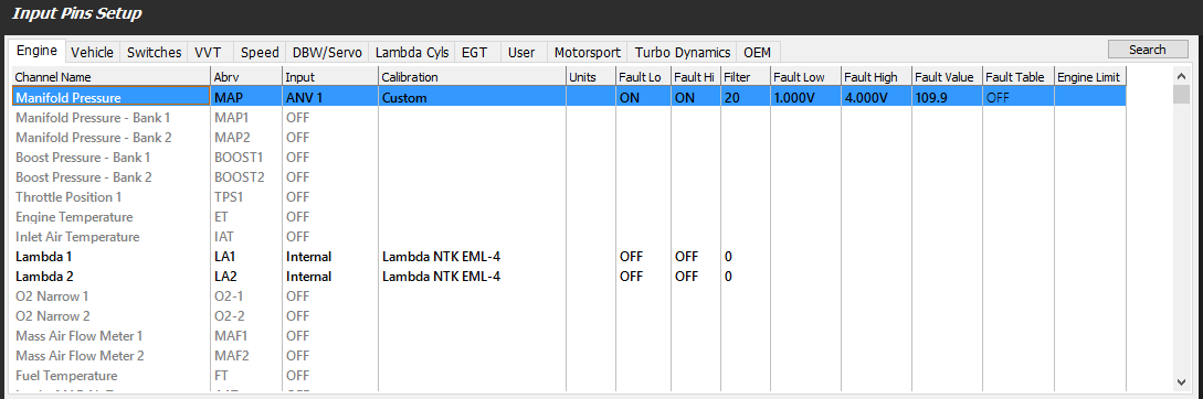
Analog voltage config window:
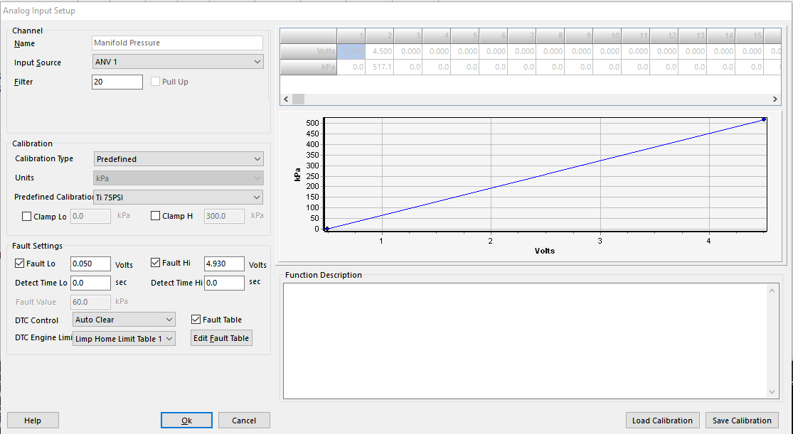
Sensor input source, filter, calibration, clamp, fault settings, fault value (substitute value), DTC control, and DTC engine limit control are all configured here. There are a number of popular “pre-configured” sensor styles.
If using thermistors, “pull up” must be switched on (only available on ANV 7-10/12).
**Digital inputs can all be pulled up, but they cannot be used for thermistors as the pull up voltage is 9.0V
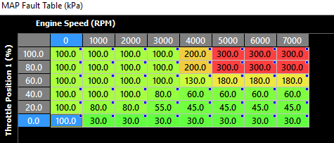
**Major sensors have the ability to enable “fault table” which allows the user to create an active look up table for substitute values.
Example below is for MAP sensor failure, using TP and engine speed to populate active substitute.
A simple switch configuration for digital input (ignition switch dedicated input):
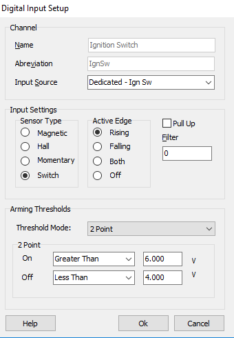
Input can be configured as a regular toggle switch, magnetic, hall, or momentary switch.
Edge configuration should be appropriately selected based on switch configuration.
Pull up can be used for ground switch inputs (2 point config would be opposite, falling edge trigger).
For high speed inputs, configuration is similar:
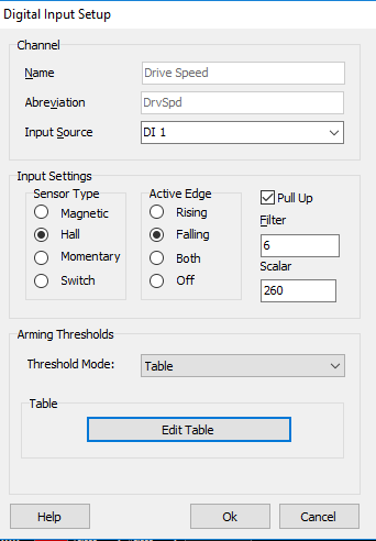
High speed inputs (DI 1-8 only) should have “table” as threshold mode, as this will specify the cross over voltage point.
This is similar to “arming thresholds” when configuring triggers
“Scaler” will facilitate the input frequency to unit conversion.
If using KV series internal Lambda sensors, select “Internal” under Input Source
If using CAN bus OEM inputs, select “CANBUS OEM” under Input Source
Custom Runtimes
Efficiency calculation is a runtime commonly used as a load point for fuel tables.
You can select from a number of Emtron calculated runtimes.
Load calculation is a runtime commonly used as a load point for ignition tables and lambda target tables.
You can select from a number of Emtron calculated runtimes.
DI Arming Thresholds
These are the tables generated by high frequency inputs when using the “table” threshold mode.
Lambda Pressure Correction
If using Lambda sensors in situations where exhaust back pressure becomes a factor (Lambda sensor installed before turbocharger or other exhaust restriction), using an exhaust manifold back pressure sensor input allows for correction of the lambda measurement.
Functions
Like Input Pins, this is a comprehensive setup that will specify all outputs to the Emtron ECU system. It has a tab structure which has a similar function to the configuration setup.
Each function that is being used can be enabled here. If there is a required output, then an appropriate output channels can be selected.
An overview of output channel functions from Emtron (see help for more details):
SL Series ECU –
AUX 1-4 Low side
AUX 5-8 Low/High side
AUX 9-10 H-Bridge (One DBW)
Spare fuel and ignition channels can be driven low side
KV Series ECU –
AUX 1-8 Low side/high side
AUX 9-12 H-Bridge (Two DBW)
AUX 13-16 Low side/high side
AUX 13-16 H-Bridge (KV12+ - Two DBW)
Spare fuel and ignition channels can be driven low side
**High side drivers and H-Bridge often need control of supply voltage to specified pin locations – see help document
Below is an example of DBW function config.
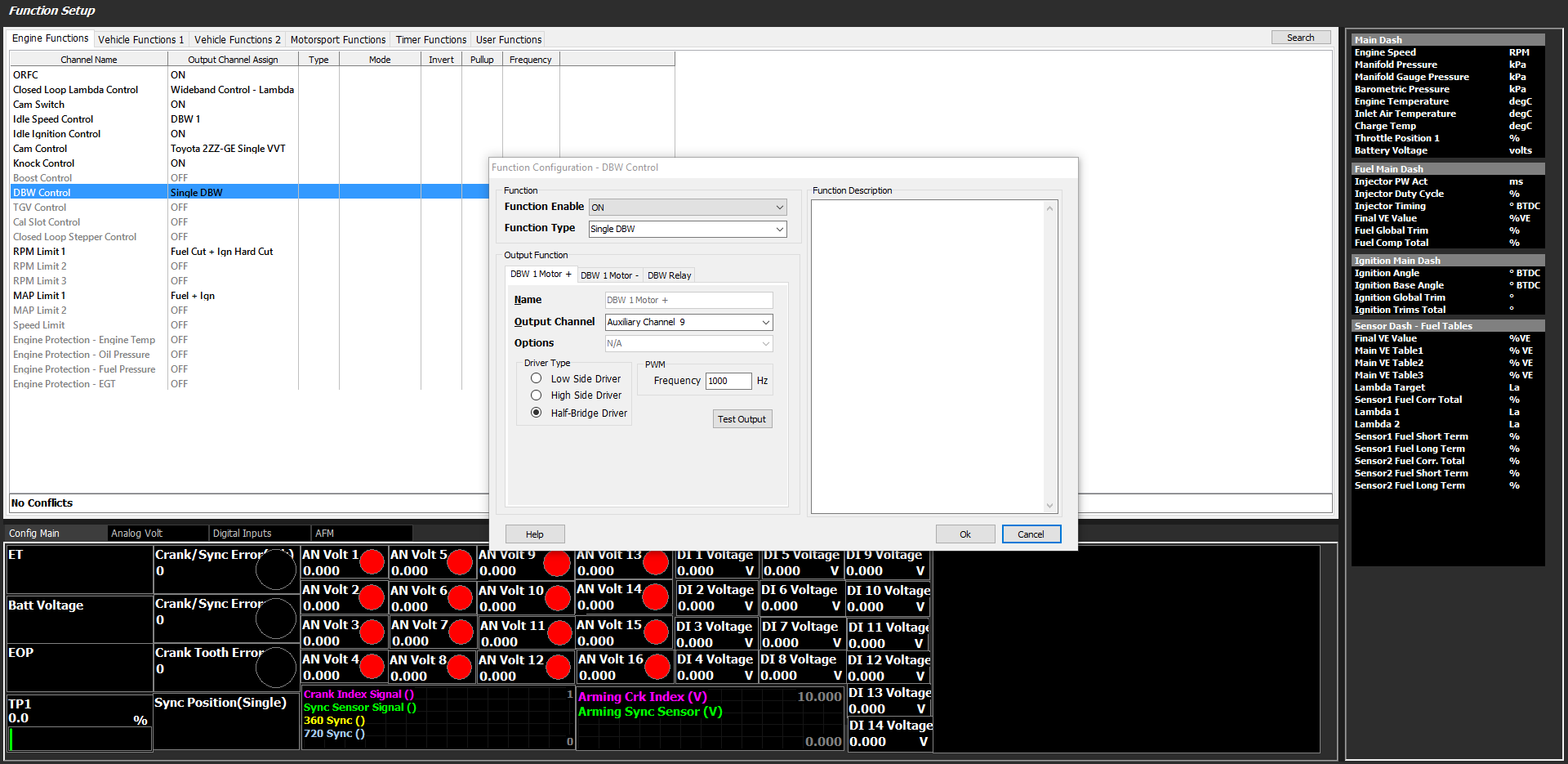
The mode for DBW is selected, the appropriate output channels, driver type (half bridge), and output frequency.
The same setup is required for any other functions that require outputs.
**See help file for specific functional setup
Communication
This section allows for setup using the Emtron CAN bus channels (2) regarding communication between auxuiliary devices such as dash systems, loggers, EGT devices, as well as Emtron CAN devices (ELC – Emtron Lambda controller).
Besides simple pre-configurations for standard logging sets, advanced setup of this system should be overseen by dealers/Emtron support. Contact your dealer or Emtron support for more assistance.