Idle Speed Control Configuration (TMF)
This section assumes the DBW has been configured and operating correctly.
The following steps should be used to configure the Idle Speed control system to work using Throttle Mass Flow.
- Configure the Throttle Mass Flow Idle Speed Control output function type using the menu:
Config -> Functions -> Function Output Setup -> Engine Functions Tab -> Idle Speed Control
Select either DBW 1 TMF or DBW 1 + 2 TMF

- Configure the throttle body model using the menu: Tuning -> Engine Function -> Throttle Body Model -> Throttle Body Setup
See Throttle Body Setup help topic for more information
- Configure the Throttle Mass Flow model using the menu: Tuning -> Engine Function -> Throttle Body Model -> Throttle Mass Flow Setup
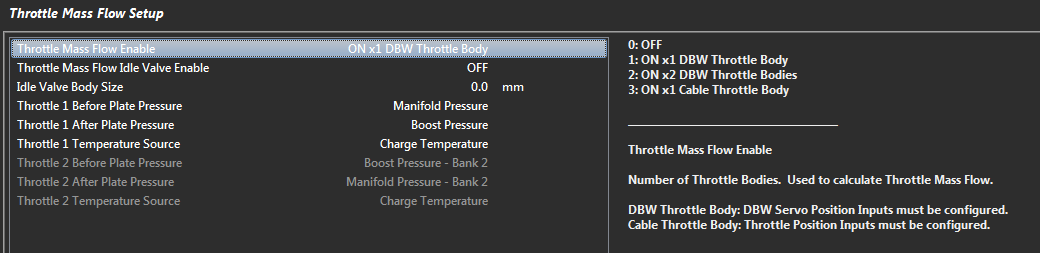
Step 1- Select the throttle mass flow enable type that is applicable to your configuration. Example: ON x 1 DBW Throttle Body
- TMF idle valve option is for TMF fuel model on cable throttle engines & is not applicable to DBW TMF idle speed control.
- The TMF idle valve size input is also only applicable to cable throttle TMF applications
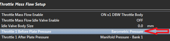
Step 2 - Set Throttle 1 before plate pressure source
- If you intend to use TMF in areas other than idle, there should be a pressure sensor already fitted before the throttle plate and this should be selected.
Example: Boost Pressure Sensor
In the case of only wanting to achieve TMF Idle Speed Control and there is no sensor fitted before the plate, simply select the internal Barometric Pressure sensor.
Other more complicated methods are also available for advanced users..
Step 3. Set the Throttle 1 After Plate Pressure source. This is normally the MAP sensor
Step 4. Set the Throttle 1 Temperature source. This is normally set to charge temperature
Repeat for Throttle 2 if applicable
Throttle Body Area Table. See Throttle Body Setup help topic for more information
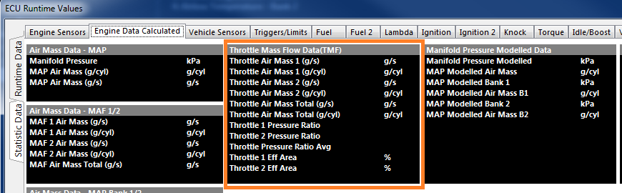
Confirm the Throttle Mass Flow calculations are operating, the data can be viewed from the Runtime menu (F3) -> Engine Data Calculated tab