Traction Control
Traction Control
The following calculated runtimes are generated by Emtron that are Traction Control related (to be further discussed more specifically):
Traction Status – The working status of the traction control
Traction Control State - The working state of the traction control
Ign Traction Trim - Ignition advance compensation
Traction Target - %Slip Target when Traction Control is active
Traction Feedforward - % feed forward when Traction Control is active
Traction Target Error – The total drive slip percentage above/below the Traction Target
Traction PID – Proportional, Integral, and Derivative gains
Traction Limit Request – Status of Traction Control being utilized in real-time
Traction Target Table – Active traction target table
Drive Slip Calculation – Percentage of slip between defined speed channels
Outputshaft Slip - Percentage of slip between Outputshaft speed source and Ideal
Outputshaft Ideal Speed - Outputshaft Ideal Speed as defined by look up table
Traction RPM Target - Outputshaft Source calculates Engine Speed
** All these runtimes can be utilized within other functions of Emtron.
** Traction Target Error for example can offset torque management functions (DBW target, Pedal Demand clamps, etc)
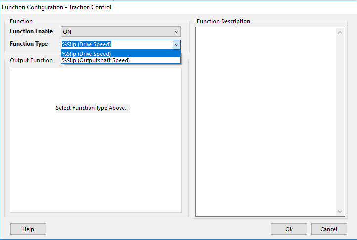
Slip Channel Mode
Emtron has two methods of generating slip channels so the traction control function can work
- Config, Function Setup, Motorsport Functions, Traction Control, Tuning, Motorsport Functions, Traction Control:
%Slip (Drive Speed)
%Slip (Outputshaft Speed)
%Slip (Drive Speed)
Drive Speed % Slip Calculation compares two speed channels to derive %Slip
Drive Slip% = (Speed Channel 1 - Speed Channel 2) / Speed Channel 2
** Runtimes for Speed Channels must be pre-configured under inputs
Configure Drive Slip Calculation system via
- Tuning, Vehicle Functions, Vehicle Dynamics, Drive Slip Calculation
Speed Channel 1
Select which calculated runtime is to be used for Speed Channel 1
** Speed Channel 1 = Normally Driven Speed Channel
0: OFF
1: Drive Speed
2: Ground Speed
3: Drive Speed Front L
4: Drive Speed Front R
5: Drive Speed Rear L
6: Drive Speed Rear R
7: Undriven Speed Front L
8: Undriven Speed Front R
9: Undriven Speed Rear L
10: Undriven Speed Rear R
11: Front Axle Speed
12: Rear Axle Speed
13: Vehicle Speed
14: Engine Speed
Speed Channel 2
Select which calculated runtime is to be used for Speed Channel 2
** Speed Channel 2 = Normally Undriven Speed Channel
0: OFF
1: Drive Speed
2: Ground Speed
3: Drive Speed Front L
4: Drive Speed Front R
5: Drive Speed Rear L
6: Drive Speed Rear R
7: Undriven Speed Front L
8: Undriven Speed Front R
9: Undriven Speed Rear L
10: Undriven Speed Rear R
11: Front Axle Speed
12: Rear Axle Speed
13: Vehicle Speed
14: Engine Speed
Slip Calculation Filter
Filters the Slip Calculation to help smooth out any pulsations
Typcial Value: 6 ( 0 = OFF)
Range: 0 - 20
%Slip (Outputshaft Speed)
Outputshaft Speed % Slip Calculation compares an Outputshaft Speed source vs an Outputshaft Speed Ideal table to derive %Slip
Outputshaft Slip% = (Outputshaft Source - Outputshaft Speed “Ideal”) / Outputshaft Speed “Ideal”
** Outputshaft Source options are :
- Outputshaft Speed Channel = ECU input using the selected source channel.
- Outputshaft Speed Calculated = Speed reverse calculated from the Wheel Speed and Final Drive Ratio
Configure Outputshaft Speed Slip system via
- Tuning, Vehicle Functions, Vehicle Dynamics, Outputshaft Speed Slip
Slip Calculation Filter
Filters the Slip Calculation to help smooth out any pulsations
Typcial Value: 6 ( 0 = OFF)
Range: 0 - 15
Outputshaft Slip Source Channel
0: Outputshaft Speed
1: Outputshaft Speed Calculated
***- Outputshaft Speed Channel = ECU input using the selected source channel.
***- Outputshaft Speed Calculated = Speed reverse calculated from the Wheel Speed and Final Drive Ratio
Traction Control Setup
Limit Type
Sets up how the traction control will cuts
0: Fuel Cut Only
1: Ign Cut Ony
2: Fuel Cut + Ign Cut
Cut Pattern
Defines cut pattern
0: Random Pattern 1
1: Random Pattern 2
2: Sequential Pattern 1
3: Sequential Pattern 2
Fuel/Ign %Cut Ratio
Allows the ratio between fuel and ignition %cut to be controlled.
0% = Requested cut all Ignition (no Fuel)
100% = Requested cut all Fuel (no Ign)
** Example: Ratio = 80%
Fuel Cut = 80% of requested Cut
Ign Cut = 20% of requested Cut
** Example: Ratio = 20%
Fuel Cut = 20% of requested Cut
Ign Cut = 80% of requested Cut
Traction RPM Target : Outputshaft Source
Channel used to calculate the Traction RPM Target
0: Outputshaft Speed Channel
1: Outputshaft Speed Calculated
2: Outputshaft Speed Ideal
- Outputshaft Speed Channel = ECU input using the selected source channel.
- Outputshaft Speed Calculated = This is the speed reverse calculated from the Wheel Speed and Final Drive Ratio
- Outputshaft Speed Ideal = This is the speed setup using the 2D Output Shaft Ideal Speed table
Traction RPM Target : Clutch Slip Channel
Channel used as Clutch Slip to calculate the Traction RPM Target
0: OFF
1: Clutch Slip
2: Clutch Slip Calculated
- Clutch Slip = Clutch Slip = (Engine Speed - Input Shaft Speed) / Input Shaft Speed
- Clutch Slip Calculated = Clutch Slip (Calculated) = (Engine Speed - Input Shaft Speed Calculated) / Input Shaft Speed Calculated
Traction RPM Target : Traction Slip Target
This enables the Traction Slip Target to correct the Traction RPM Target
0: OFF
1: %Slip Target
Example: Output Shaft Speed = 2000 RPM
Clutch Slip = 21%
Gear Ratio = 2.056
Traction Slip Target = 8%
Traction RPM Target = 2000 x 2.056 x 1.21 x 1.08 = 5373 RPM
Traction Control Lockouts
RPM Lo Lockout
Traction Control will be OFF below this Engine Speed.
Typical : 1500 RPM
0 = OFF
RPM Hi Loclout
Traction Control will be OFF above this Engine Speed.
Typical : 200 RPM below RPM limit
0 = OFF
TP Lo Lockout
Traction Control will be OFF below this Throttle setting.
Typical : 5.0 %
0 = OFF
TP Hi Lockout
Traction Control will be OFF above this Throttle setting.
0 = OFF
%Slip Lo Lockout
Traction Control will be OFF below this %Slip.
Typical : 5.0 %
User Lockout
Create a custom lockout using a User Channel.
When the channel is ON the lockout is active
Traction Table Control
Selects the active Table Control method of the Traction Control
0: Tables OFF
1: ON - Table 1
2: ON - Table 2
3: ON - Table 3
4: Not Available
5: ON - Cal Slot
6: ON - Z-Axis
Traction Target Tables
These look up table define the amount of %Slip to be maintained by the ECU. Slip below the value will generate a positive Traction Target Error, while slip above the value will generate a negative Traction Target Error. Slip above the value triggers the ECU to cut engine torque by use of fuel/ignition cuts, timing retard, or other connected functions.
See the following examples:
A simple fixed value for traction control to become active

Traction Target vs Front Axle Speed
** Rear axle as Drive Speed
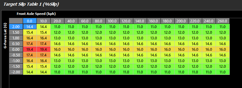
A more comprehensive table utilizing internal G-Force sensor (Lateral Accel)
** Rear axle as Drive Speed
** G-Force sensor must be pre-configured
Traction Slip Offset Tables
Like any other “offset” table in Emtune, these tables add to the main target tables. Tables can be configured to use any runtime, and spanned in 3D.
See the following example:
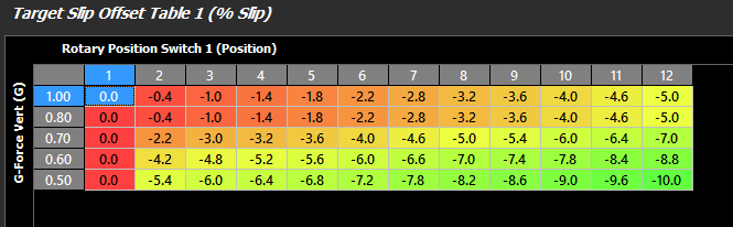
A more comprehensive use of the offset table utilizing KV series Internal G-Force sensor (Verticle Force), and a Rotary Position Switch to change the final Slip Target.
** G-Force sensor must be pre-configured
** Rotary Position Switch must be pre-configured
Ignition Retard Tables
Amount of ignition retard the traction system can employ once the system is active. Tables can be configured to use any runtime, and spanned in 3D to enhance flexibility.
See the following example:
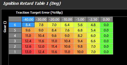
** Gear Recognition must be pre-configured
** Retard is being applied here only when the Traction Target Error is negative, meaning the %slip is above the Traction Target.
Traction PID setup
Traction Deadband +/-
The output control signal is held constant when the Input Signal (DriveSlip) falls within the deadband range of the Setpoint (Slip Target). This helps reduce steady state error and oscillations.
Typical: 0.20 %
Integral Positive Clamp
Used to clamp the contribution of the integral term in the PID loop and prevent Integal Windup.
Typical Value: 20.0 %
Integral Negative Clamp
Used to clamp the contribution of the integral term in the PID loop and prevent Integal Windup.
Typical Value: - 20.0 %
Slip Target Filter
Filters the Target signal to help smooth out any pulsations
Typcial Value: 6 ( 0 = OFF)
Range: 0 - 10
Feed Forward %Cut Table
Emtron uses a Feedforward Table for a base %Cut for the PID function to operate from.
This allows for very fast response as the ECU has a basic lookup table for %Cut to function from before the PID is applied.
See the following example:
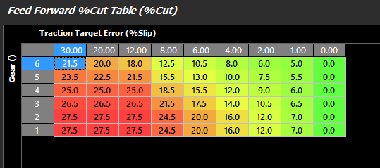
A more comprehensive use of the Feed Forward %Cut table utilizing the Traction Target Error calculation and gear recognition.
** Gear Recognition must be pre-configured
Proportional Gain Table
Proportional gain controls how aggressive instantaneous correction must be vs Target Error.
This parameter can be expanded into a 3D look up table to provide greater accuracy regarding closed loop control.
Integral Gain Table
Integral gain controls how much adaptive correction is needed.
This parameter can be expanded into a 3D look up table to provide greater accuracy regarding closed loop control.
Derivative Gain Table
Derivative gain controls predictive correction. This function is used to prevent overshooting targets by looking at a number of factors like rate of change, and P and I gain.
This parameter can be expanded into a 3D look up table to provide greater accuracy regarding closed loop control.
Traction Max Cut Table (% Cut)
This clamps the maximum cut the traction control can apply based on the entered values.
See the following example:
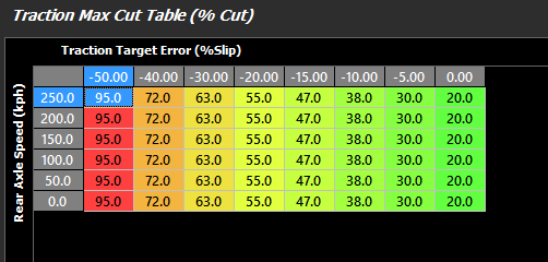
** Rear Axle Speed must be pre-configured