Gearshift Control Tuning
Gearshift Control Tuning
The first step in the tuning section of the function is to setup the gear request input method.
…………..
Gearshift Compressor Setup
Tuning View -> Motorsport Functions -> Gearshift Control -> Gearshift Compressor Setup
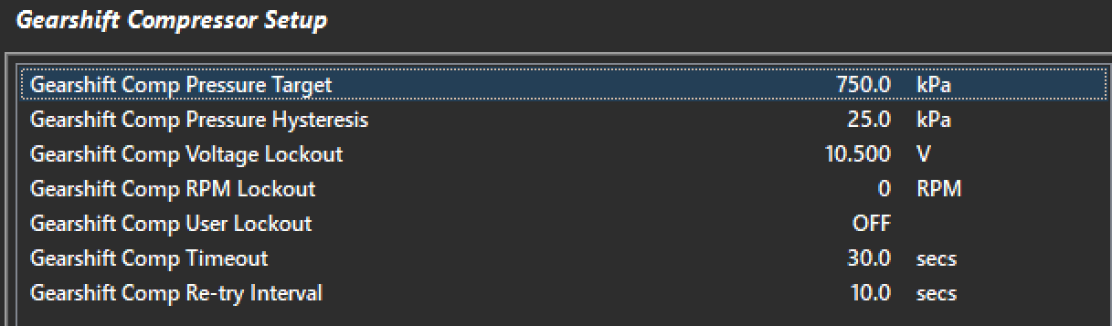
Gearshift Comp Pressure Target
The target compressor pressure represented in kpa. The transmission manufacturer should be able to advise on the maximum pressure to operate with however common settings are between 600-800kpa.
Gearshift Comp Pressure Hysteresis
The amount the compressor pressure needs to drop below the target before the compressor is switched back on. Ideally the supply pressure should be kept as constant as possible for consistent shift performance.
Gearshift Comp Voltage Lockout
Minimum ECU supply voltage to allow the compressor to operate.
Gearshift Comp RPM Lockout
Minimum Engine Speed to allow the compressor to operate. This is usually set to reduce battery load while the vehicle supply is powered.
Gearshift Comp User Lockout
A user channel may be used to lockout the compressor if the default lockouts are not satisfactory for the application.
Gearshift Comp Timeout
If the compressor target is not reached within this time the ECU will assume there must be a fault in the system. Most common faults would be a leak or faulty compressor motor.
Gearshift Comp Re-Try Interval
Once the compressor pressure target is not reached within the time out the ECU will wait for the re-try interval and attempt to turn on the compressor again.
Upshift Setup
Tuning View -> Motorsport Functions -> Gearshift Control -> Upshift Control -> Upshift Setup
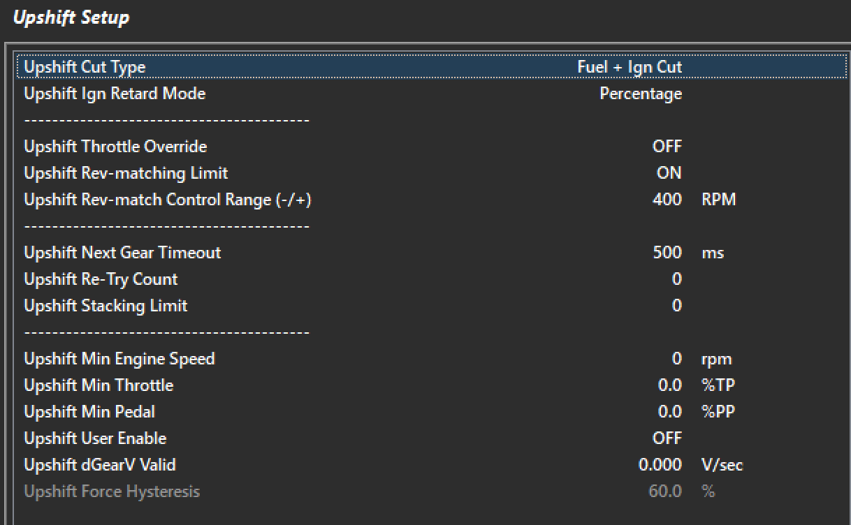
Upshuft Cut Type
This sets the type of cutting used for gearshift control.
Fuel Cut Only
This system will cause a slower recovery of the engine from the cut leading to longer overall effective shift times. The will lead to quieter operation on the gearshift due to lack of unburnt fuel in the exhaust to ignite.
Ignition Cut Only
This system will cause very fast recovery as the fuel film does not require rebuilding after the shift recover. Depending on the tuning strategy and hardware careful consideration needs to be taken when choosing this cutting method. Unburnt fuel igniting in the exhaust can lead turbocharger and exhaust damage. Valve train needs to be considered also when choosing this system.
Fuel + Ign Cut
This system employs a combination of both fuel and ignition cutting strategies. This system is generally the most favored method as there is a lot of flexibility with the cut strategy balance.
Upshift Throttle Override
The ECU can override the DBW throttle position during and Upshft event. Generally for the fastest shifting performance cutting and retard strategies alone will allow will achieve the best results. During low traction surface shifting is can be possible to help unload the dog by closing the throttle during the shift.
Upshift Rev-matching Limit
This setting toggles the rev matching feature. The ECU can perform a user level cut strategy which then leads into the Engine Speed Limit rev-matching strategy. It is advised to always have this feature enabled for best performance.
Upper Rev-match Control Range (+/-)
This is the range the Engine speed limit controls the cut %. For upshift this should be a positive(+ve) number. 400rpm is a good starting range. Once the engine is within 400rpm of the ECU calculated rev-match target cut will commence.
Upshift Re-Try Count
The ECU employs a strategy of retrying the shift if it is deemed to have either failed or will fail based on a the in coming sensor data.
Upshift Next Gear Timeout
This is the timeout allowed for the upshift event to occur in total. All cutting and instructions should have completed within this time. If the gear has failed to achieve a shift and upshift counter will increment. All retries would have occured within this timeout.
Upshift Stacking Limit
The ECU has the ability to increment a shift request counter for the purpose of “stacking” shifts. This number limits the amount of shifts that can be stacked. When the conditions are satisfied a shift will occur and the stack count will decrement until the count reaches zero.
Upshift Min Engine Speed
Upshift Min Throttle
Upshft Min Pedal
Upshift User Enable
Downshift Setup
Rev-matching describes the process of matching engine speed to the gear you are shifting into/requested gear. With Downshifting the Engine Speed must be increased so additional air needs to be introduced with the ECU supporting a variety of methods. This reduces stress on the drive-line.
The Downshift setting can be found in the Tuning View -> Motorsport Functions -> Gearshift Control -> Downshift Control menu.
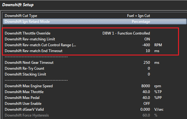
Downshift Cut Type
This setting is used in 1) The Pre-Cut Downshift function which allows the “dog” to be unloaded 2) For Rev-Matching
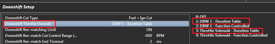
Downshift Throttle Override
Allows additional air to be introduced into the engine on downshift. There are 5 options:
0: OFF
1: DBW 1 - Duration Table
2: DBW 1 - Function Controlled
3: Throttle Solenoid - Duration Table (Non DBW application)
4: Throttle Solenoid - Function Controlled (Non DBW application)
The “Duration Table” is an open loop control. A table is used to enter in the length of time the Downshift Throttle Override will be active
“Function Controlled” allows the ECU to dynamically change the Throttle Override time based on the functions state. For example as the Gearshift “Next-Gear Stable” time varies, the ECU dynamically adjusts the Throttle Override time to match.
NOTE: You can use this function with the Rev-matching OFF. However, there is nothing limiting the engine speed so caution should be used when setting the amount of additional air introduced into the engine.
Downshift Rev-matching Limit
The Downshift Rev-matching Limit function will Limit the engine RPM to match the requested downshift gear. The ECU uses the transmission gear ratios between the current gear and requested gear to calculate a Rev-matched RPM Limit Target.
Make sure the Downshift Rev-Match RPM Target Correction table is setup correctly. Initialise to 0% for first time setups.
Additional air MUST also be introduced into the engine, either by using the DBW or a solenoid to manual open a cable throttle. The ECU will control this with options available in the Downshift Throttle Override setting.
Downshift Rev-Match Cut Control Range
Controls the RPM Range over which the engine will be cut when the Downshift limit is active. The Min Cut and Max Cuts are locked respectively at 0% and 95%
Example:
Rev-match RPM Target = 4000
Min Cut = 0%
Max Cut = 95%
1) Range = +400 0RPM,
Engine Speed: 4000 RPM = 0% Cu
Engine Speed: 4400 RPM = 95% Cut
2) Range = -400 RPM (Recommended)
Engine Speed: 4000 RPM = 95% Cut
Engine Speed: 3400 RPM = 0% Cut
Downshift Rev-Match End Timeout
The Rev-match Limit will be removed once the DBW has returned to within 5% of its normal position. This Timeout allows additional time for the system to stabilize before the limit is removed. If this setting is required typical times range from 10 - 50ms.
NOTE: This setting ONLY applies to DBW applications. If not used set to zero.
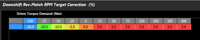
Downshift Rev-Match RPM Target Correction Table
Applies a percentage correction to the calculated Rev-Match Target. The range is +/- 100%.
Example:
Rev-match RPM Target = 4000
Driver Torque Demand = 25Nm
Based on the below table the %Correction is 5%.
Final Rev-match RPM Target = 4000 x 1.05 = 4200 RPM
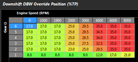
Downshift DBW Override Position Table
Sets the Servo Position target that the DBW will move to during the downshift. This is an absolute position. The below table shows a typical 4 cylinder engine example.
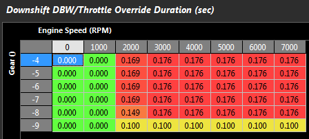
Downshift DBW/Throttle Override Duration Table
The length of time the air override system is introducing additional air during the downshift. This can be a Solenoid pushing on a cable throttle or DBW. This table is only enabled when the Downshift Throttle Override setting is non-function controlled i.e. Open Loop Duration Table as shown below.
Final Example
In 4th gear, downshifting to 3rd:
Downshift Rev-Match Control Range = -400 RPM
Current rpm = 6000
Gear ratio 4th = 1.000
Gear ratio 3rd = 1.230
Downshift Rev-Match RPM Target Correction = 2%
Target Downshift RPM = 6000 x 1.230/1.000
Target Downshift RPM = 7380
Apply 2% Target Correction:
Target Downshift RPM = 7380 x 1.02
Target Downshift RPM = 7527
Downshift RPM High: 7527 RPM at 95% Cut
Downshift RPM Low: 7127 RPM at 0% Cut
So the ECU will Limit the Engine Speed between 7127 and 7527 assuming sufficient air has been introduced