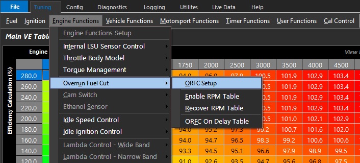
ORFC Setup
ORFC Setup
 \
\
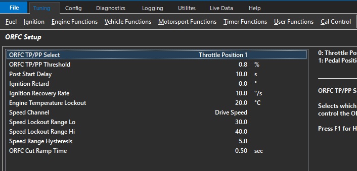
ORFC TP/PP Select
Selects which input is used to control the ORFC
0: Throttle Position 1
1: Pedal Position
ORFC TP/PP Threshold
When the TPS 1 or PPS value is below this setting the Over Run Fuel Cut can become active.
** Follows ORFC TP/PP Select
\
Post Start Delay
Delay after the engine has been started before ORFC can become active
Ignition Retard
Ignition Retard from the total ignition advance when ORFC is active
Ignition Recovery rate
Rate which the ignition Overrun Fuel Cut Ignition Retard is decayed to 0 once the engine has recovered.
Typical : 10 deg / sec
Engine Temperature Lockout
Engine Temperature that must be exceeded before ORFC can become active
Speed Channel
Used to define how the “Speed Lockout” is used.
\
0: OFF
1: Drive Speed
2: Ground Speed
3: Drive Speed Front L
4: Drive Speed Front R
5: Drive Speed Rear L
6: Drive Speed Rear R
7: Undriven Speed Front L
8: Undriven Speed Front R
9: Undriven Speed Rear L
10: Undriven Speed Rear R
11: Front Axle Speed
12: Rear Axle Speed
13: Vehicle Speed
14: Engine Speed
15: Input Shaft Speed
16: Output Shaft Speed
\
** Speed inputs must be defined and properly calibrated under “Input Setup”
Speed Lockout Range Lo
\
Speed below which ORFC cannot become active\
Speed Lockout Range Hi
\
Speed above which ORFC cannot become active\
Speed Range Hysteresis
\
Hysteresis to prevent Overrun Fuel Cut becoming active on the threshold of a speed lockout value.
Example : A speed Lockout Range Hi setting of 60 and a Speed Range Hysteresis setting of 5 will not allow Overrun Fuel Cut to become active until Speed has reduced to 55 after being over 60.
ORFC Cut Ramp Time
\
Used to progressively increase the cut from 0% to 100% over the specified time.
Allows for a smoother transition into the Fuel Cut.