Idle Speed Control Setup (TMF)
Idle speed control Setup (TMF)
Tuning –> Engine Functions –> Idle Speed control –> Idle Speed Control setup (TMF)
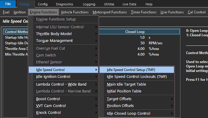
Control method
Used to select either Open or Closed Loop.
Open Loop mode is generally used to setup initial settings before using Closed Loop mode.
0: Open Loop
1: Closed Loop
** Closed Loop applies PID functions to Idle Feed Forward
** Idle Feed Forward is derived from Idle Initial Position + any comp tables
Start-up idle hold time:
How long the ECU is required to remain at the predetermined flare rpm on start up.
This additional rpm target is added in the Start-up Offset target Table
The additional air flow required to allow this to occur correctly is added in the Idle Speed Control - Initial position table (g/s) at the required idle speed at the given temperature.
Please note: The Initial position table when in open loop mode is just that, the initial position in g/s of airflow that the engine will target. Once closed loop TMF idle control is activated, the Idle Speed Control – Initial Position Table (g/s) becomes the feed forward table for TMF closed loop idle. It is no longer an initial position, rather it is an expected value that feeds into the TMF idle speed PID control strategy. The values to be set in this table are arrived at when using the TMF Idle speed control in Open Loop control much as one would with Open & Closed Loop Boost control (See Idle Speed Control – Initial Position Table (g/s)
Start-up idle decay rate:
This function sets the rate of decay to idle in rpm per second that engine speed reduction is applied; from the start up offset target rpm (Flare) to the idle target rpm once the engine is running and the start-up idle hold time has expired (See above)
Throttle area demand (idle) clamp:
The throttle area clamp is a safety feature that prevents the DBW servo from exceeding a set throttle body area percentage at idle and prevents unintended values when calibrating the function.
This value is directly related to the values previously imputed into the Throttle body area table
A typical value is 10% - this refers to 10% throttle area, not DBW servo position or TPS
See Throttle body set up – throttle body area table
Min Throttle area blend pedal to idle:
This is the threshold below which the Pedal Throttle Area Demand starts to blend
into the Idle Throttle Area Demand
A typical value is 6% area