Idle Speed Tuning Guide
Idle Speed Tuning Guide
Idle Speed Tuning
Idle Speed Control in Emtune has comprehensive functions. There are a multiple tuning parameters, target, and position compensations.
Ignition timing is a contributing factor to engine idle speed. Please make sure you have reasonable timing being commanded by the ECU to make idle speed configuration go smoothly and function consistently.
** If planning to use idle ignition control, the static value for tuning idle speed should be in between the working range of the idle ignition control for both systems to be affective.
Example: Idle Ignition Clamp 0-25 degrees. Lock timing at 12.5 degrees.
Commanding ignition timing off the main ignition table is recommended for first startup of an engine. The values in the main table can later be edited once functions (like Idle Ignition Control) are subsequently added.
Tuning Idle Speed Control
Regardless of the system being used, starting idle speed control in open loop is best.
Initial Position:
Tuning -> Engine Functions -> Idle Speed Control -> Initial Position Table
This is the feed forward position for the idle speed control.
The value in this table is constant regardless of idle speed lockouts, except if DBW or DBW TMF modes.
** Initial Position can always be compensated by Position Offsets
Example: Idle Target = 800rpm
Idle Position = 37.5% (with closed loop enabled)
Idle speed is then locked out due to throttle position and engine speed (10%TP, 3000PRM)
Initial Position = 40%
Idle Position = 40% until lockouts are satisfied (engine rpm, TP, etc)
Units in this table vary depending on the Idle Speed Control method used,
IE - Stepper count for stepper motor, Duty cycle for solenoid, DBW position, or Target Throttle Mass Flow
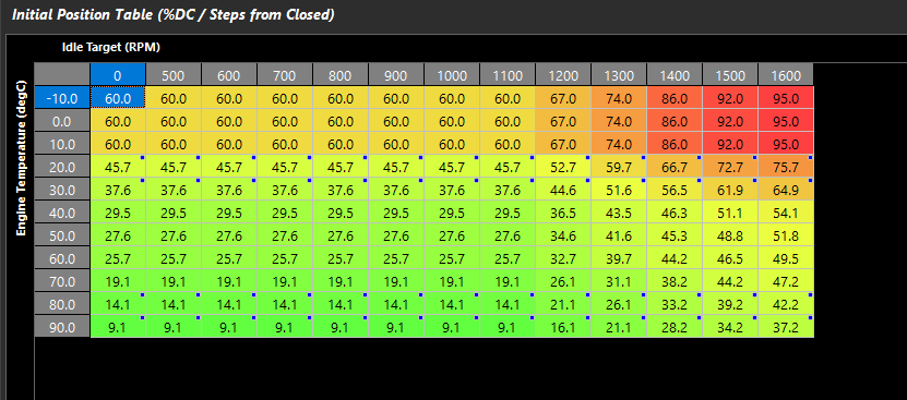
It is recommended to configure one of the axes of the Initial Position table to an Idle Target Speed (Main Idle Target, see below).
Initial Position can be compensated several ways under:
Tuning -> Engine Functions -> Idle Speed Control -> Position Offsets
** Position compensations (comp tables) add/subtract to the initial position
** This is the feed forward if closed loop control is used
Main Idle Target:
Tuning -> Engine Functions -> Idle Speed Control -> Main Idle Target Table
This table allows you to build an idle target speed in RPM
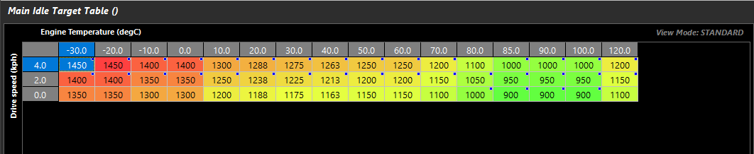
Like all Emtron tables, different runtimes are available for axis configuration making the system very flexible.
** This table is active if the Idle Ignition Control function is turned on as well.
Once you have a base set up for initial position and main idle target, match the initial position to target idle speed during different engine environmental conditions (most commonly engine temperature).
With this properly configured, going back to the Main Idle Target Table in different operating conditions should make the engine speed change and match the target accordingly.
** A good open loop configuration is the basis for enabling Closed Loop Control.
Main Idle Target can be adjusted by several offset tables under:
Tuning -> Engine Functions -> Idle Speed Control -> Target Offsets
Closed Loop Control
Depending on the system being used, closed loop settings will vary. Basic PID tuning principles apply.
See specific examples below for notes on individual systems regarding Closed Loop (when applicable)
2 Wire Idle Solenoid
A Two Wire Idle solenoid is generally supplied power and the ECU Aux Output pulse the other pin to open the valve.
Units in position tables are in %Duty
Typical frequencies for 2 Wire Idle Solenoids are 50-250hz
Closed loop:
2 Wire Idle Solenoids often have a default air bleed position when they are not powered (failure position). The min and max deviation from the initial position when using closed loop must be carefully configured so the idle valve does not fall into those ranges while the engine is running. Otherwise the idle engine speed will not be able to be controlled.
Example:
0-20% = default position air/bleed. At 0% (same as being powered off), the idle valve is flowing air through the mechanical default air bleed to prevent engine stall. It then closes completely at 20%.
20-100% re-opens the idle valve with precision. This is the range the ECU must operate in for good idle speed control.
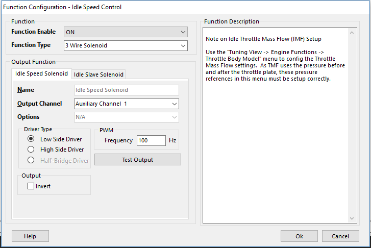
3 Wire Idle Solenoid
A 3 Wire Idle solenoid is generally supplied power from the EFI Relay circuit and the ECU Aux Outputs pulse the second and third extra pins to open and close the valve.
The Idle Speed Solenoid output should be the opening winding.
The Idle Slave Solenoid output should be the closing winding.
Units in position tables are in %Duty
The ECU mirrors the opposite of the opening duty on the slave channel (closing wining), providing more accurate open loop positioning vs 2 wire idle solenoids.
IE –
Idle Speed Solenoid Output 75%
Idle Slave Solenoid Output 25%
Idle Speed Solenoid Output 30%
Idle Slave Solenoid Output 70%
The frequency of the valve is configured in output setup (See Idle Speed Setup).
Typical frequencies for 3 Wire Idle Solenoids are 50-250hz
Bi-Polar/Uni-Polar Stepper Motor
DC Stepper Motors convert rotation into step counts which the ECU can move incrementally to change the amount of air bleeding around the closed throttle. See wiring guides regarding wiring different types of stepper motors.
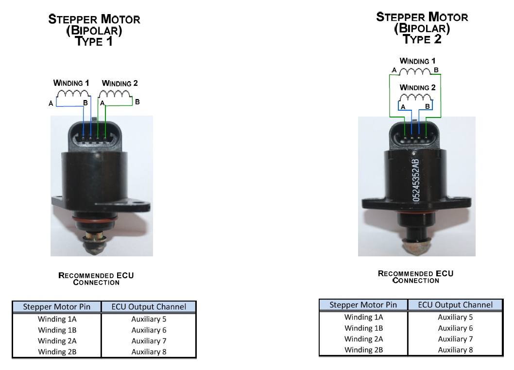
Units in position tables are in Steps from Closed position
** Stepper Valves have extra settings such as “Closed position is reset either at Key On/Off” under:
Tuning -> Engine Functions -> Idle Speed Control -> Idle Speed Control Setup
DBW (1, 1 + 2)
When set to DBW 1, or DBW 1+2, the ECU will use the DBW motor position to control idle speed of the engine.
Units in position tables are in raw DBW position.
** DBW Control must be fully configured
** DBW PID must be set up accurately to ensure precision during Idle Speed due to the air flow being very sensitive to airflow vs DBW position (especially with a large throttle body).
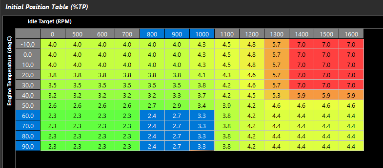
Setting Initial Position Table
A good way to initially set up DBW motor position is recommended to lockout idle speed completely and work off the Pedal to Throttle Demand Table:
Tuning -> Engine Functions -> Torque Management -> Pedal to Throttle Demand Translation Table
Once the engine is idling at the appropriate RPM, use Runtimes to look at what the raw DBW position/Throttle Position to populate the Initial Position Table.
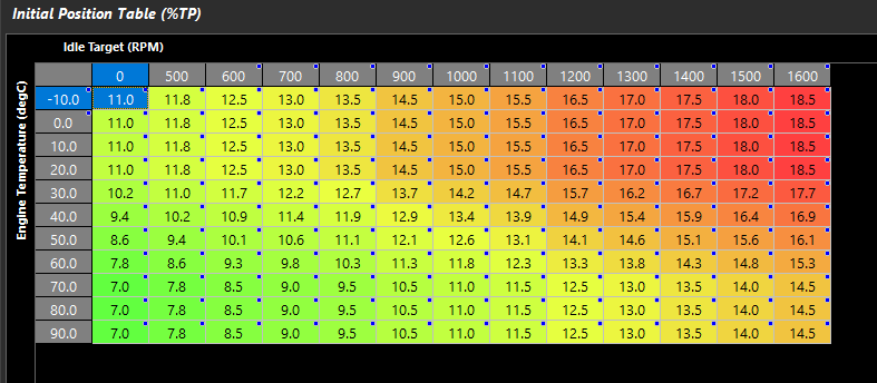
Initial Position built off above examples at operating temperature. Estimation for extra air flow can be extrapolated regarding colder temps and blended as shown (must be checked on cold start).
** Position is much more sensitive to air flow than solenoids or stepper motors
Transitioning smoothly from Idle Speed to Pedal Demand
Because the Idle Speed Control Initial Position is controlling the DBW target, when the idle speed control is locked out (pedal is pushed), the DBW target will transition back into the Pedal to Throttle Demand Table. It is important to have a minimum position that corresponds to somewhere close to the idle Initial Position. If 0% (or a lower number than Idle Initial Position) is targeted in the Pedal Demand Table, the engine may stall/stumble due to lack of airflow.
Initial Position Highlighted
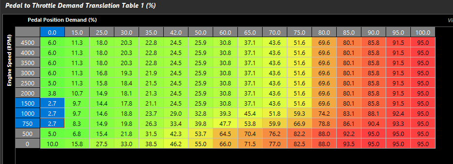
Pedal Demand Highlighted
** Throttle Body Area Table is 1:1 in this example
** If Throttle Body Area is worked out, then Pedal to Throttle Demand Translation Table will not match DBW initial position, and the raw position needed will need to be matched vs Throttle Body Area
** If Throttle Body Area Table is worked out, then Idle Speed Control mode should be DBW 1/1 + 2 TMF
Closed loop:
Using Closed Loop Control with DBW Idle Speed Control (%TP/%DBW Servo Posn) requires much less aggressive PID settings and limits. The reason for this is only a small change to the DBW position is needed to make a large affect on airflow.
For initial setup use the following PID settings:
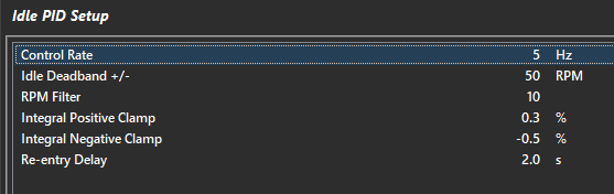
Proportional Gain Table = 0.00
Integral Gain Table = 0.025
Derivative Gain Table = 0.00
Min/Max Deviation from Initial Position Table = +/- 1%
The above settings will limit how quickly the Closed Loop will change the initial position, and limit how far the throttle can be moved from the initial position.
** Final settings will probably have less minimum deviation than max deviation for Anti-Stall functions