TMF Idle Speed Control
Introduction
Throttle Mass Flow (TMF) as the name indicates, is the rate at which air mass is flowing through a throttle body in units of grams/second (g/s).
The flow through a throttle body is governed by three physical elements:
- Conversation of mass
- Newtons second law of motion for fluids
- Conservation of energy
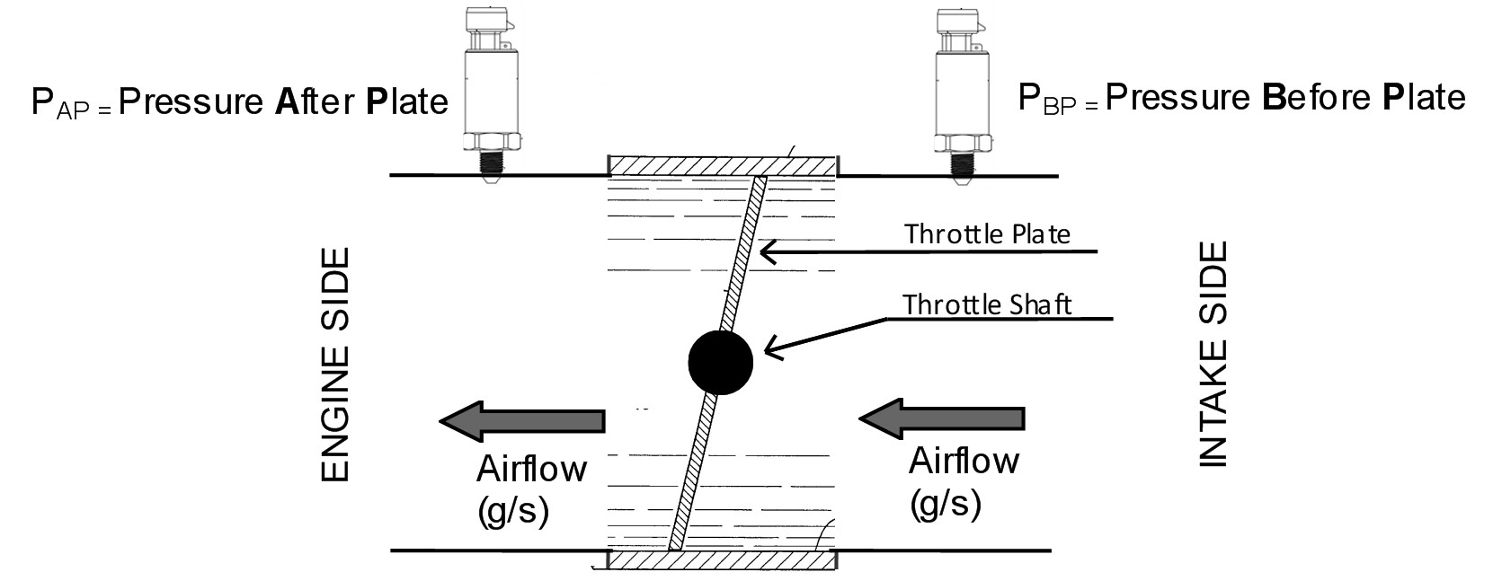
By combining all these elements the ECU can model the flow of fluid through the throttle body accounting for throttle plate thickness and throttle shaft size. One key piece of data is knowing the pressure ratio across the throttle body as shown in the below diagram, the other key piece of data is the current throttle area. If the pressure ratio and throttle area is known, the ECU can very accurately calculate the mass flow rate through a throttle body.
Although the ECU completes these complex calculations internally, the process of calculating Throttle Mass Flow is kept as simple as possible for the user with the following inputs and setup required:
Inputs required
- Pressure Before the throttle Plate
- Pressure After the throttle Plate
Setting required
- Throttle Body Size
- Throttle Area to Servo Position Correlation Table (Throttle Body Area Table)
The TMF calculation can summarised in the below equation :
| Throttle Mass Flow (g/s) = ( Pafter / Pbefore) x Throttle Area x Modelled throttle body fluid dynamics equation |
|---|
Throttle Mass Flow Idle Speed Control
The Throttle Mass Flow (TMF) idle speed control function delivers extremely accurate and rapid idle calculation based on actual engine’s airflow requirements. Any engine load change will be detected by a pressure ratio change across the throttle body allowing the ECU to make instantaneous corrections. In all DBW applications we strongly recommend that the TMF Idle speed control is employed. TMF Idle speed control is an independent idle speed control function that utilises the Emtron’s comprehensive air mass flow modelling without effect on the fuel model used.
The Throttle Mass Flow (g/s) becomes the target flow for the Idle Speed Control system i.e how much air mass flow is required for a given target rpm. So the TMF becomes the feed-forward/Initial value. The ECU will then apply a PID correction to this flow target until the Target RPM is reach. By rearranged the TMF equation, the ECU will convert the final Throttle Mass Flow(g/s) into Throttle Area and move the plate to that position. A feed-forward/Initial value table example is shown below.
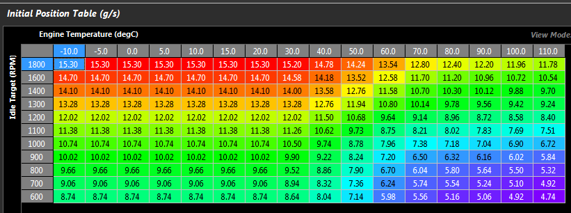
Typical TMF Idle Feed forward table in units of g/s
NOTE:
Any fuel model mode can be selected and does not need to include TMF for the TMF idle speed control function to work correctly.
TMF fuel model is covered in the Fuel section and not discussed here.
Warning - DBW setup must be completed before setting up TMF idle