4: Mass Air Flow Sensor (MAF) + AirMass Modelled (Blend)
Mass Air Flow Sensor + Air Mass Modelled (Blend)
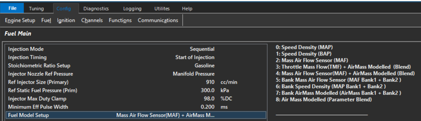
A Blend Table generates a Final Air Mass using a ratio from the MAF Sensor and Air Mass Modelled.
The following MAF input channels can be used:
- Mass Air Flow Sensor(s) 1 and 2
OR
- Mass Air Flow Bank Sensor(s) 1 and 2 can be used
The ECU will search which channel(s) are enabled and use those inputs. “Mass Air Flow Sensor” takes priority over “Mass Air Flow Bank Sensor”. For example if both
Mass Air Flow Sensor1 and Mass Air Flow Sensor2 input channels are configured the ECU will automatically use both inputs.
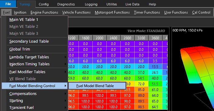
The fuel model blending control table is accessed from : Tuning -> Fuel -> Fuel Model Blending Control
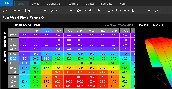
0% = Air Mass Modelled ONLY
100% = Mass Air Flow Sensor ONLY
Air Mass Modelled setup must be configured - Air Mass Modelled Setup
Mass Air Flow setup must be configured - Mass Air Flow Meter 1 Input
** Blend tables must be configured completely before tuning
Mass Air Flow tuning/re-scaling is accomplished by generating and validating a Secondary Load Table. This allows
the MAF sensor scaling to adjusted under different user conditions:
Example. MAF value of 10.0 g/s and scaling of 25% will yield a scaled MAF value of 12.5 g/s.
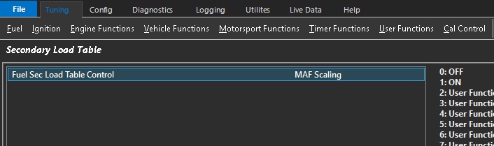
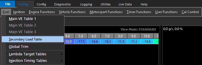
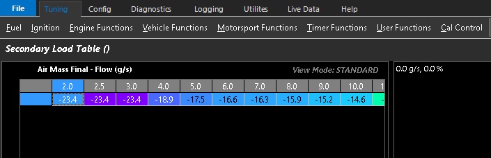
The secondary load table becomes a primary tuning table when linked to the MAF scaling
To tune the secondary load table the fuel model blend table is set to 100%