2: Mass Air Flow Sensor (MAF)
Mass Air Flow Sensor
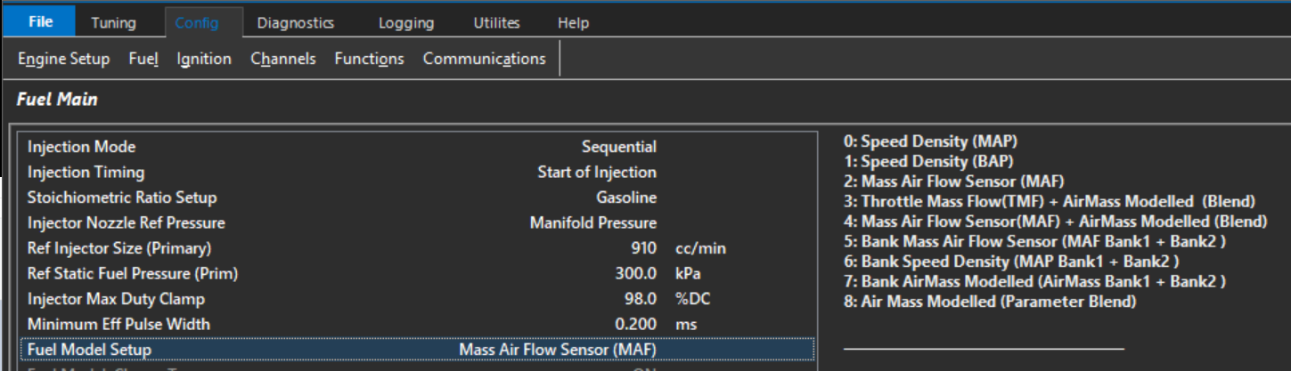
The Air Flow Sensor(s) provides a measured Air Mass Flow in g/s. The ECU then converts this into air mass per cylinder (g/cyl) giving actual Air Mass into the Engine.
The following MAF input channels can be used:
- Mass Air Flow Sensor(s) 1 and 2
OR
- Mass Air Flow Bank Sensor(s) 1 and 2 can be used
The ECU will search which channel(s) are enabled and use those inputs. “Mass Air Flow Sensor” takes priority over “Mass Air Flow Bank Sensor”. For example if both
Mass Air Flow Sensor1 and Mass Air Flow Sensor2 input channels are configured the ECU will automatically use both inputs.
MAF systems are more flexible in their ability to compensate for engine changes(like altitude and IAT) since they actually measure airflow instead of calculating it like the Speed Density Fuel Model. It also greatly reduces the tune time as you no longer need to adjust the fueling based on the VE of the Engine… its automatically accounted for by the MAF sensor.
However they also have limitations around restriction and sensor range on high power engines.
Once the Mass Air has been measured, if the MAF requires further scaling this can be done using a 3D Table. In the real world “small” corrections will need to be applied. This can be done using the Secondary Load Table which will allow a +/- percentage correction to be applied.
A Typical example is shown in below. Table Control should be used to put the Secondary Load Table into this “special” mode shown below
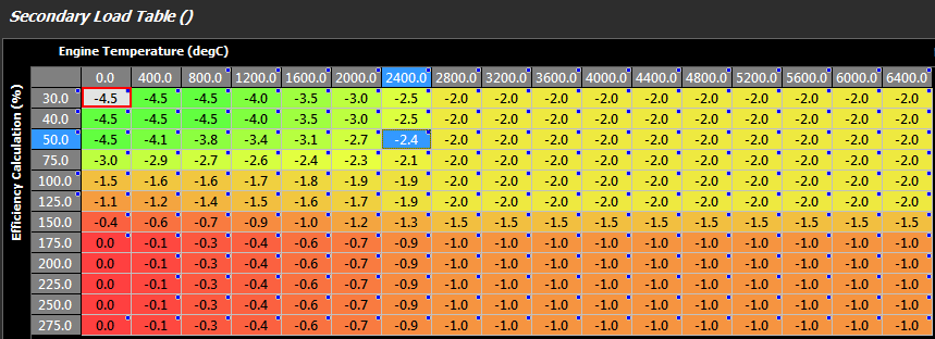
Secondary Load Table used for MAF Sensor
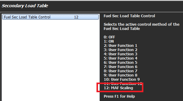
Table Control for Secondary Load Table
Once the Air Mass has been determined, the Stoichiometric Ratio and Lambda Target are used to generate a Fuel Mass (g). The Stoichiometric Ratio will vary with Fuel Type. A Single Zone if the fuel type is fixed can be used or a Table allowing the ECU to constantly correct for varying alcohol content.
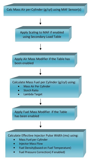
Once the Fuel Mass is determined, the Effective Injector Pulse Width can be calculated using:
-
- Injector Size
- Fuel Density. Fuel Density can be a function of both Fuel Temperate and Alcohol Content.
- Fuel Pressure Correction. The Fuel Pressure Correction is a Fluid Dynamics equation, also called Bernoulli’s equation.
It allows the injector Flow Rate to be adjusted as the differential pressure across the injector changes.
NOTE: This correction MUST be enabled using the “Fuel Model : Fuel Pressure” setting
Flow Chart Overview for Mass Air Flow Sensor Fuel Model: