Fuel Model Overview
In both Speed Density and MAF modes the ECU performs the following steps to calculate the final Injector OpeningTime.
- Calculate the Air Mass per cylinder.
In Speed Density Mode PV = nRT is used to Calculate Air Mass.
In MAF mode, Air Mass is measured directly from the MAF Sensor.
In Throttle Mass Flow (TMF) mode the Air Mass is calculated by looking at the pressure ratio across the throttle body, calculating the
throttle area and applying these to a 2nd order thermodynamics equation.
- Calculate Fuel Mass using Air Mass, Stoichiometric ratio, Lambda Target, Engine VE and other parameters outlined below.
- Calculate Effective Pulse Width using Fuel Mass, Injector Mass Flow, Fuel Density and Bernoulli’s equation for Fuel Pressure correction.
Fuel Model: Charge Temp
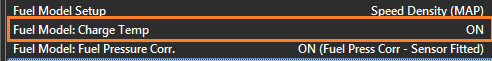
This setting ONLY applies when the Fuel Model is selected to Speed Density. There are 2 separate methods that control how the fueling is adjusted based on Charge Temperature.
- With this setting set to ON (and this is the recommended setting) the Charge Temp will be used to adjust the Air Mass as part of the Ideal Gas Law equation. The ECU is then able to automatically adjust the Air Mass (g) based on this temperature.
- When this setting is OFF the Air Mass is not modified base on Charge Temp. Instead the Tuning View -> Compensations -> Charge Temp Comp Table 1 can be used to manually correct the fueling based on Charge Temperature.
NOTE: It is NOT recommended to have both systems ON at the same time.
Fuel Model: Fuel Pressure
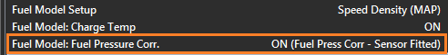
This setting applies to ALL Fuel Models. A Fuel Pressure Sensor MUST be fitted. The ECU will correct/adjust the Injector Flow as the differential pressure across the injector changes. This means any fuel surge causing an sudden drop in fuel pressure the ECU can correct the fueling and maintain the correct mixture.
NOTE: Fuel Pressure Units MUST be in kPa to match both the MAP and BAP units.
Sensor Requirements
Additional to MAP and MAF the following sensors should be used to take full advantage of ECUs Fuel Model(s):
Fuel Temperature.
Used to help accurately calculate Fuel Density (g/ml) by spanning the x-axis on the Fuel Density Table (see Config View -> Fuel -> Fuel Density Table). See Figure 1 below.
If the Fuel Temp channel is not selected it defaults to 20 DegC which will then be used to span the Fuel Density Table. Note: If an Ethanol Sensor is selected the Fuel Temp information from the sensor is automatically copied into the Fuel Temp Runtime.
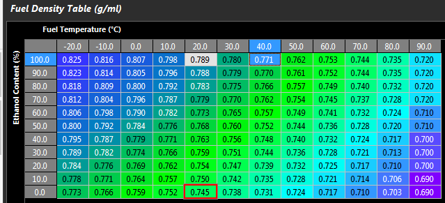
Figure 1: Fuel Density Table
Fuel Pressure Sensor.
Required if Fuel Pressure Correction is to be used.
Ethanol Sensor
Strongly recommended to use this sensor when running Ethanol based fuels. It allows the ECU to automatically correct fueling based on Ethanol Content. i.e Petrol (0% Ethanol) up to 100% Ethanol. It does this by adjusting the Fuel Density and Stoichiometric Ratio . See Figure 1.
The Final Air and Fuel Mass used by the ECU can be viewed from the Runtime menu -> Fuel Tab (F3). You can also view data from the Speed Density (SD) and MAF Sensor Calculations. See Figure 2.
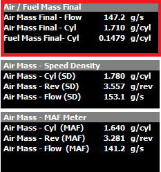
Figure 2. Final Mass values (Fuel and Air) shown in red box.
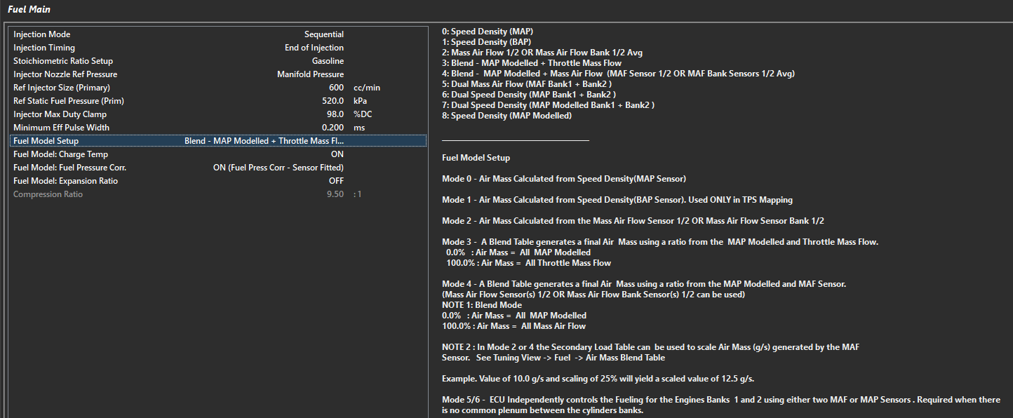
Fuel Model Modes
To configure the Fuel Model select the appropriate method from the Config View -> Fuel -> Fuel Main -> Fuel Model Setup
Air and Fuel Mass Modifier Tables
There are additional Tables available to modify the Air Mass and Fuel Mass if required. These can be switching ON from Tuning View -> Fuel Table Control -> Mass Modifier Tables. See Figure 3.
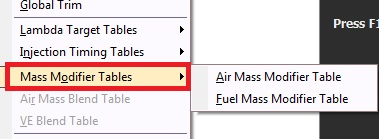
Figure 3: Mass Modifier Tables