CAN Bus Termination
3.4 CAN Bus Wiring
✍ CAN Bus High and Low are differential signals, so twisted pair MUST be used. Failing to do so will compromise the entire CAN Bus System.
✍ 🖐◼ 🞟🞏🔾♏ ♏⌧⧫❒♏🔾♏ ♏◼❖♓❒🞏◼🔾♏◼⧫🞟📪 shielded twisted pair may be required to help with reliability and data integrity.
✍ The less connectors in any transmission system the better. Unnecessary connectors are almost guaranteed to present an impedance discontinuity and hence may cause reflections and data loss.
✍ CAN Bus termination must be done correctly by using a 120 ohm 0.25W resistor at each END of the bus system.
✍ Maximum Stub length to a device from the main Bus is recommended at 0.3m, in accordance with High-Speed ISO 11898 Standard specification. See Figure 3.3.
The ELC devices do not include an on-board CAN termination resistor, allowing the device to be wired at any position on the Bus. CAN Bus termination must be done correctly by using a 120 ohm 0.25W resistor at each end of the bus system as mentioned above. Figures 3.1 and 3.2 show possible CAN Bus Implementation examples
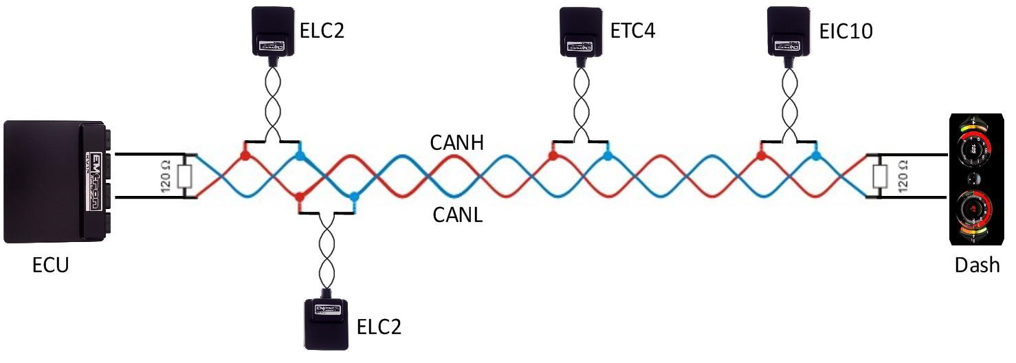
Figure 3.1. CAN Bus Wiring Example. ECU and Dash at each end with 120 Ohm Termination
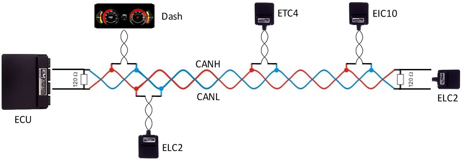
Figure 3.2. CAN Bus Wiring Example. ECU and ELC2 at each end with 120 Ohm Termination EMTRON ELC USER MANUAL WWW.EMTRON.WORLD
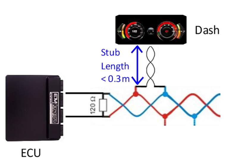
Figure 3.3. CAN Bus Wiring Example. Stub Length less than 0.3m