DBW TMF Idle
DBW (1 TMF, 1 + 2 TMF)
When set to DBW 1 TMF, or DBW 1+2 TMF, the ECU will use the DBW motor position to control idle speed of the engine based on a target Throttle Mass Flow of air. For DBW applications, this function is superior to any other type of idle speed control, especially with the closed loop function.
This method of Idle Speed Control is possible due to the Emtron system being able to calculate airflow through the Throttle Body using Throttle Mass Flow.
The function is a concept of providing base idle air mass speed for the engine to idle.
This simply put means you are telling the ECU how much airflow is required to run the engine at idle engine speeds, instead of a “idle position”.
Units in position tables are in raw grams per second (g/s).
** DBW Control must be fully configured
** DBW PID must be set up accurately to ensure precision during Idle Speed due to the air flow being very sensitive to airflow vs DBW position (especially with a large throttle body).
** Throttle Mass Flow must be enabled and turned on - and calculating TMF Air Mass g/s values
Setting Initial Position Table
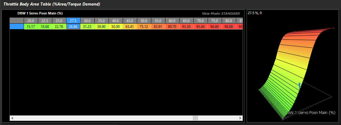
Throttle Mass Flow is the target for the idle speed control system, The Throttle Body Area table must be configured in the Throttle Body Model. See Throttle Mass Flow
Tuning -> Engine Functions -> Throttle Body Model -> Throttle Body Area Table
This is the expected airflow in g/s for the engine at a given idle rpm & temperature. A channel Air Mass Final – Flow g/s, generates the actual airflow consumed by the engine.
Use this runtime to help set the values in this table. The more accurate this table is, the better the closed loop idle control will function
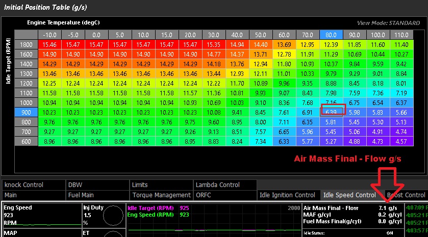
** Air Mass Flow Final - Flow is only valid if your TMF air flow calculation is correctly set up and matching speed density and other mass air flow functions - assuming that your Air Mass Flow Final = the calculated Throttle Mass Flow. In some cases with high error between the mass flow calculation, and TMF - TMF Air Mass should be used
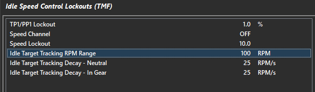
Idle Target Tracking RPM Range and Decay
Tuning -> Engine Functions -> Idle Speed Control -> Idle Speed Control Lockouts (TMF)
Idle Target Tracking RPM Range raises the idle target when locked out until the Idle Speed Lockouts are satisfied again. This adds a “dashpot” function to the system, the Idle Speed will go to the Idle Speed Target PLUS the Target Tracking RPM.
Idle Target Tracking Decay then subsequently removes the Target Tracking Range in RPM/second
Good staring numbers are as follows:
Idle Target Tracking RPM Range = 100
Idle Target Tracking Decay = 25
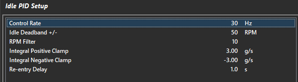
Closed loop:
TMF Closed Loop control is superior to standard DBW Position Idle Control due to higher resolution targeting Mass Flow vs small DBW position changes.
For initial setup use the following PID settings:
Proportional Gain Table = 0.50
Integral Gain Table = 0.050
Derivative Gain Table = 0.25
Min/Max Deviation from Initial Position Table = +/- 3.00g/s
* Tuning Tip -
Idle by DBW can be unstable by nature, due to resolution of airflow at lower positions not being metered very accurately. The concept should be as such : use the idle speed control system to provide a base airflow for the engine to run, then use the Idle Ignition Control system to help control the idle speed torque.
If you have instability with the system due to the DBW plate moving around too aggressively, reduce closed loop gains, and limit the closed loop control (min/max deviation tables).