Crank/Sync Sensor Arming Threshold Settings
Crank/Sync Sensor Arming Threshold Settings
When the Arming Threshold for Crank or Sync sensors is not set correctly, Crank or Crank/Sync errors are general the result causing error count, misfires, no start conditions, etc. The Scope can help identify the issues and allow configuration changes to fix the errors.
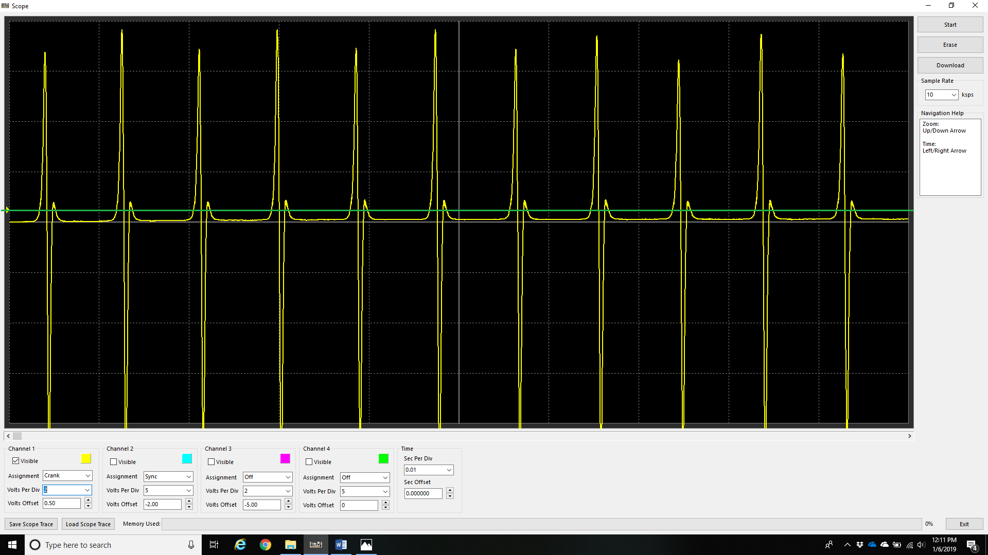
The above example shows a crank trigger with a Crank Sensor Arming Threshold set too low (represented by the green line) – 0.5v).
Setting the Arming Threshold (as described in Crank/Sync Sensor Arming Threshold), states for the signal to be valid the voltage must go above this voltage.
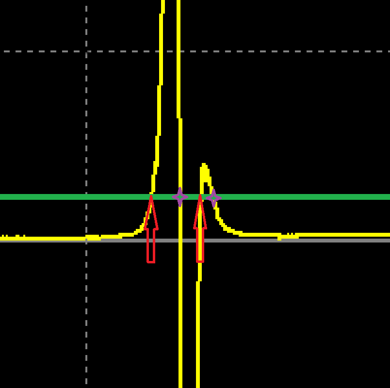
The above example shows the signal crossing the arming voltage (red arrows) twice, and subsequently in purple where the ECU is triggering a “tooth” position as a result of the signal. One clearly is a tooth, and one is false trigger.
Lifting the arming voltage above the false trigger in this situation will filter out the second erroneous trigger.
** A normal characteristic of a magnetic sensor requires lifting of the voltage as the RPM of increases. This is a good characteristic of a magnetic trigger anyways, as since the voltage of the sensor is increasing, you can filter out any interference in the lower voltage ranges as well. Emtron trigger inputs can also handle high signal amplitude (100V +/-).
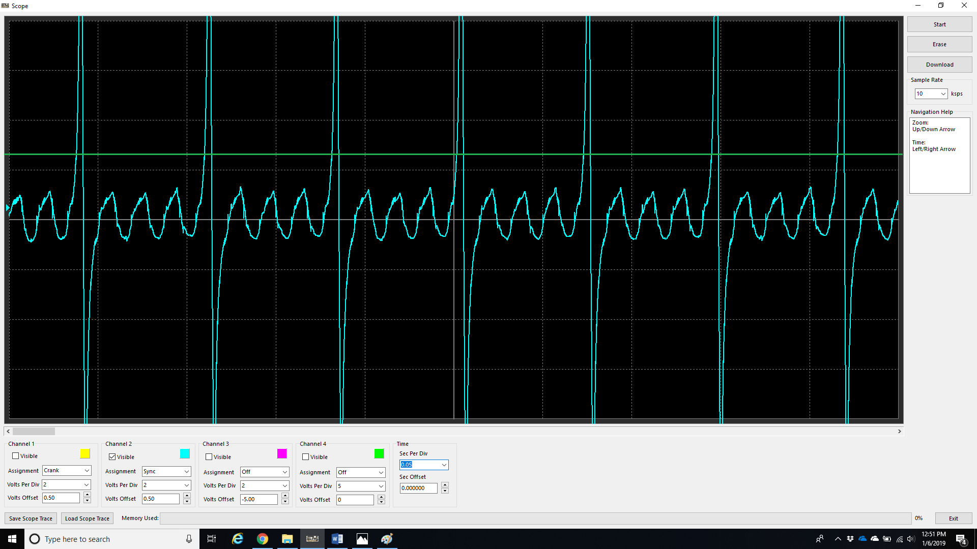
A good example of Sync Sensor Arming Threshold = 2.5v.