Improper Edge Configuration for Crank/Sync Sensor
Falling Edge
With correct sensor polarity, both magnetic and hall sensors should have falling edge polarity in most cases. This is because these sensors have consistent “fast” performance when the tone ring teeth pass the sensors.
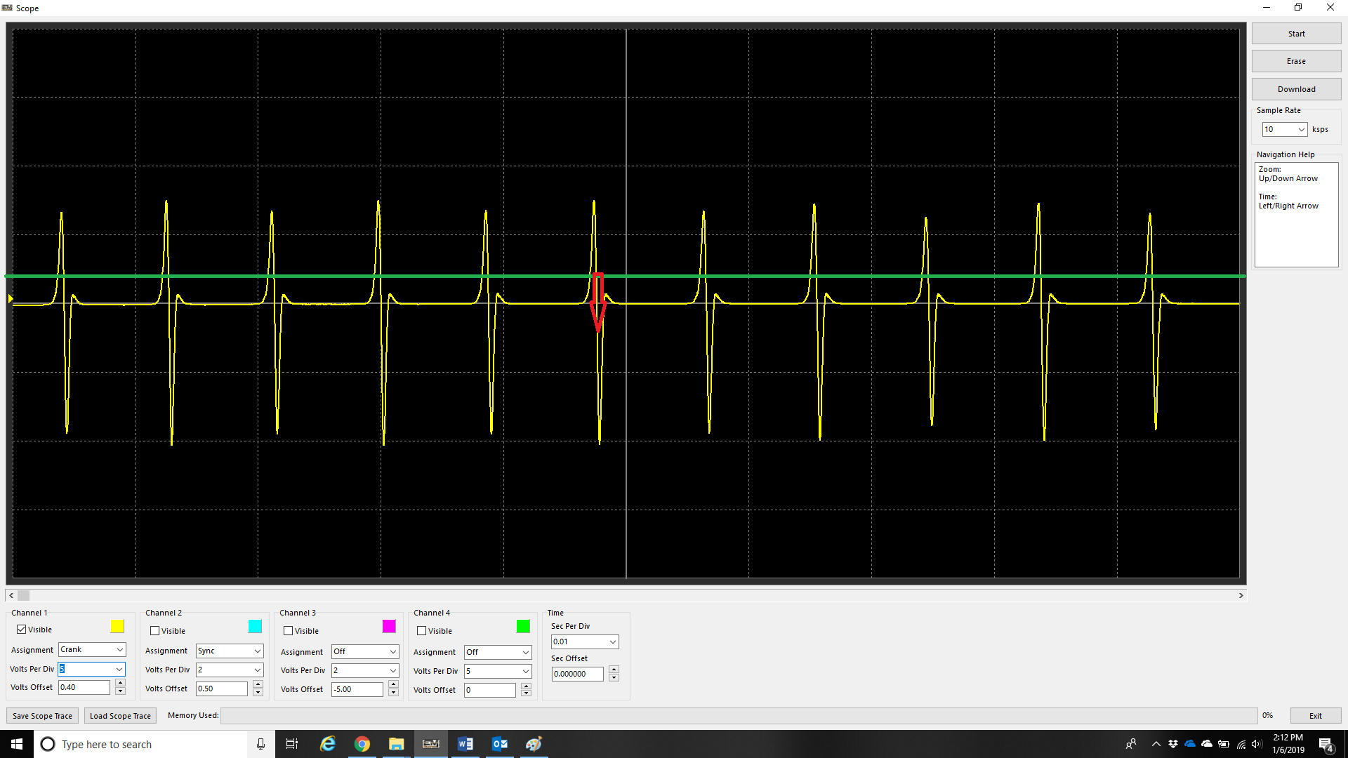
An example of a magnetic sensors fast edge being the falling.
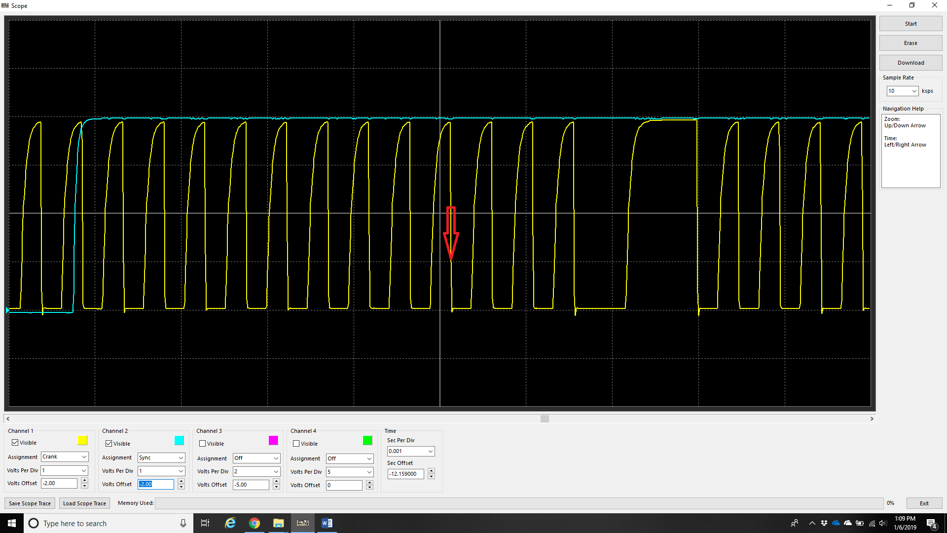
An example of a hall senor fast edge being the falling. Most hall sensors produce a very good “square” wave, so the point can be argued that rising edge can be used, however at higher revs some will produce this “saw tooth” pattern which means triggering that way will cause timing to wander.
Rising and Falling Edge Sync Mode
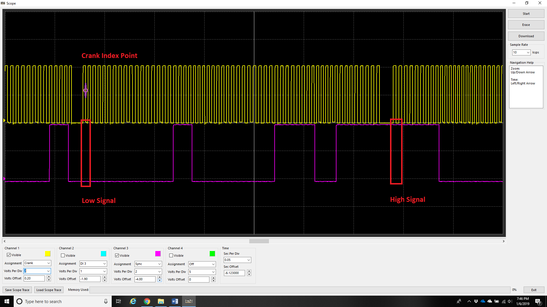
Engines with multi-tooth sync sensors usually will have a “long” tooth during the “crank index point”. Normally, a custom decoding mode is needed to run the engine with multiple sync teeth, but in this case because there is a clear difference in signal on the sync input on each stroke (low vs high), the ECU can determine the stroke immediately (this is the fastest way to decode starting/720 sync). Set Sync Sensor Edge configuration to Rising and Falling for these trigger types.
** See Sync Sensor Setup – Sync Sensor