DBW Closed Loop tables
DBW Feed Forward %DC Table
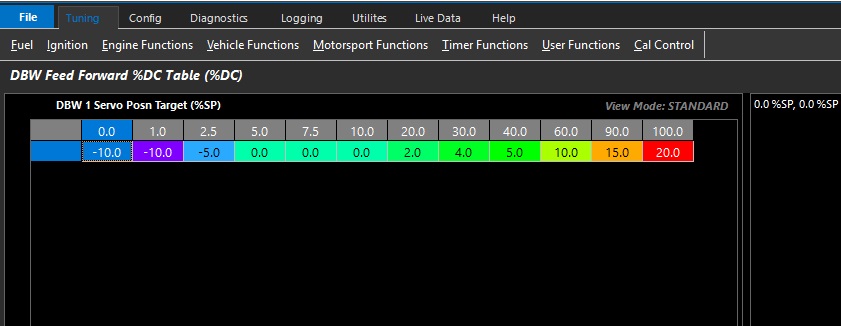
Emtron uses a Feed Forward Table to provide a base duty for the PID function to operate from.
This allows for very fast response as the ECU has an initial lookup table before any PID is applied.
This table can be expanded into 3D (X axis enabled), and any runtime can be used.
DBW Proportional Gain Table
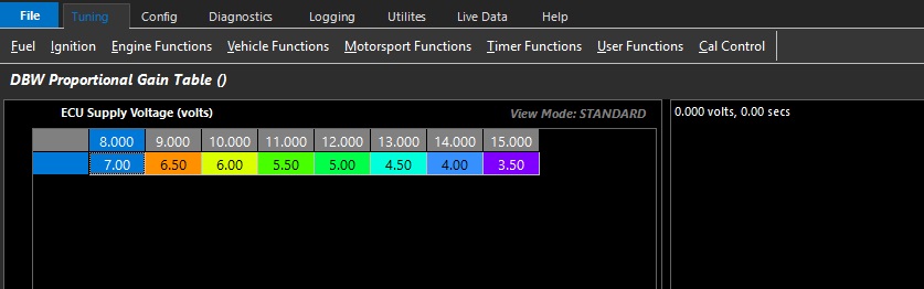
Proportional gain controls how aggressive instantaneous correction must be.
This table can be expanded into 3D (X axis enabled), and any runtime can be used.
Above is an example where the change Proportional Gain is spanned across Battery Voltage.
DBW Integral Gain Table
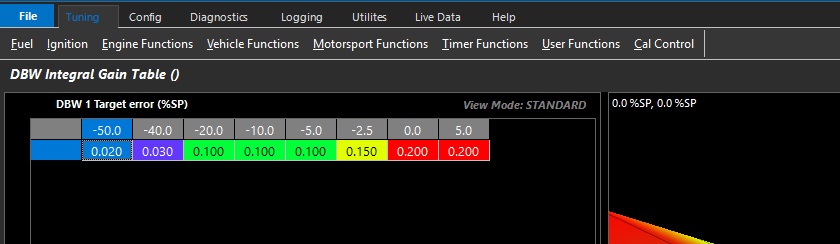
Integral gain controls how much adaptive correction is needed.
This table can be expanded into 3D (X axis enabled), and any runtime can be used.
DBW Derivative Gain Table
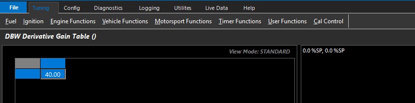
Derivative gain controls predictive correction where gain is based on the rate of change of error.
This function is used to prevent overshooting targets by looking at a number of factors like rate of change, and P and I gain.
This table can be expanded into 3D (X axis enabled), and any runtime can be used.
DBW Min Duty Clamp Table
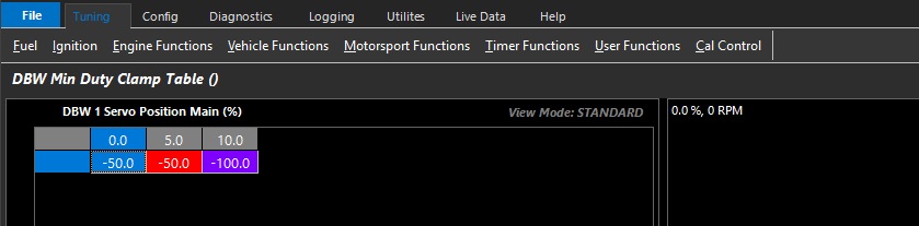
Allows the user to set the minimum duty cycle that can be used by the closed loop system.
This table can be expanded into 3D (X axis enabled), and any runtime can be used.
DBW Max Duty Clamp Table
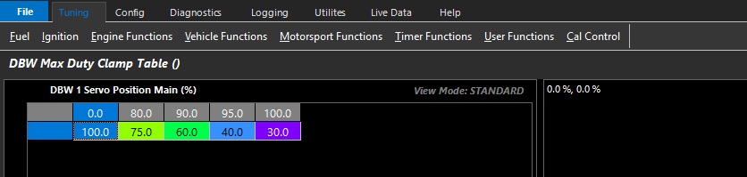
Allows the user to set the maximum duty cycle that can be used by the closed loop system.
This table can be expanded into 3D (X axis enabled), and any runtime can be used.
DBW Pos Integral Limit Table
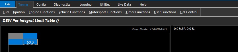
Allows the user to set the maximum I gain compensation used by the closed loop system.
This table can be expanded into 3D (X axis enabled), and any runtime can be used.
DBW Neg Integral Limit Table
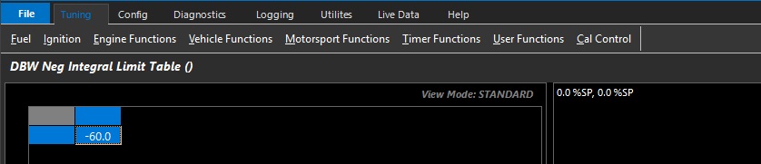
Allows the user to set the minimum I gain compensation used by the closed loop system.
This table can be expanded into 3D (X axis enabled), and any runtime can be used.
NOTE:
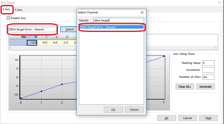
** If using dual DBW, then axis for target errors should be selected as “shared” runtimes. This tells the PID system to look at the respective DBW to apply closed loop gains
Tuning DBW PID
The DBW servo position is controlled in the Torque Management section.
The Pedal to Throttle Area Demand Translation Tables control the driver demand translation into throttle area demand.
The relationship between throttle area demand & DBW servo position is validated in Throttle Body Model > Throttle Body Area Table
The Pedal to Throttle Area Demand Translation Table does not relate to DBW servo position directly
To tune the DBW PID, it is useful to reconfigure the target function & zero the Pedal Position Demand Filter
For the purpose of tuning the PID, change the Pedal to Throttle Area Demand Translation Tables and the Throttle Body Area Table to be linear.
This will deliver a 1:1 relationship
Once PID control is validated, return to non linear Pedal to Throttle Area Demand Translation Tables & validate the Throttle Body Area Table
See Torque Management – Throttle Mass Flow
See Torque Management – Pedal to Throttle Demand Translation Table
See Throttle Body Setup - Throttle Body Area Table