Calculated Channel Examples
Calculated Channel Examples
Calculated Channels are accessed via the File Menu.
A “new” channel can be created, where the user can define name, abbreviation, min/max, units, etc.
There are pre-defined Math Functions that can be selected, in which the Maths Function Description will dictate how it can be used.
Derivative Speed Example
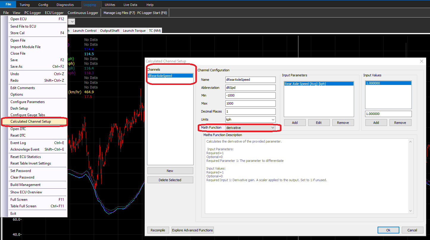
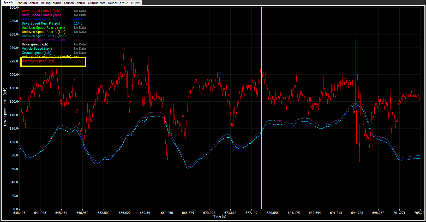
The example above is showing how the derivative math function can be used to create a channel for the Rear Axle Speed channel.
Once created, the channel can be selected in the logger, live dash, or programmed as a Set Cell Value (Q).
Simple Channel Re-naming
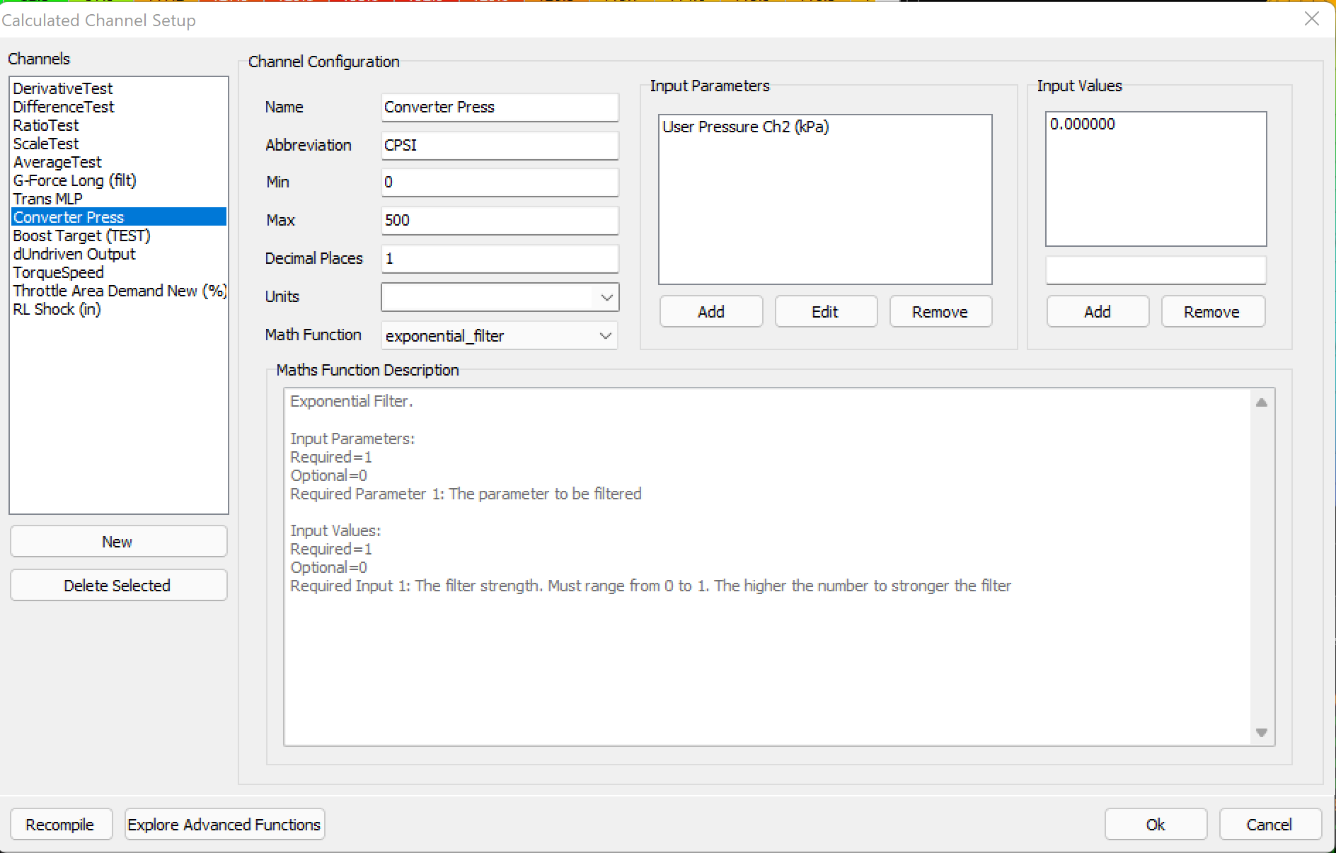
The example above is showing how the User Pressure 2 channel name is being converted to a name that can be easily displayed.
The Exponential Filter math function is being used (a math channel MUST be selected), however the filter strength being set to 0.000 will output a 1:1 value in the logger exactly as the User Pressure 2 channel is being reported
** A different math function can be used, such as “sum”, with no actual sum (0.000).
Channel Re-naming with math
In some cases, channels may need re-naming, but also an offset applied to them. Most commonly if a sensor needs a simple way to “zero” it’s value. Instead of re-scaling the sensor in the sensor input every single time, this can be done in the calculated channels.
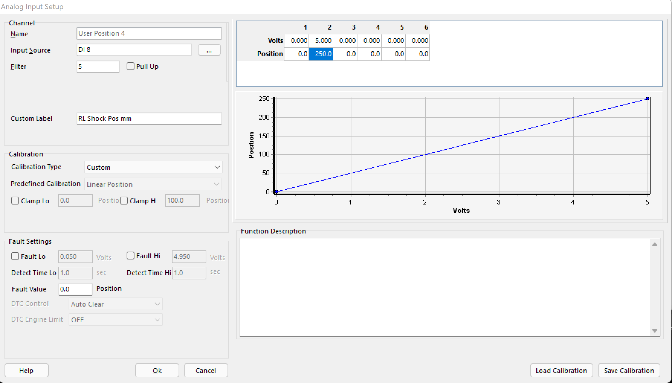
A User Position is set up here for a rear shock sensor.
The voltage range represents it’s complete range (0-250mm)
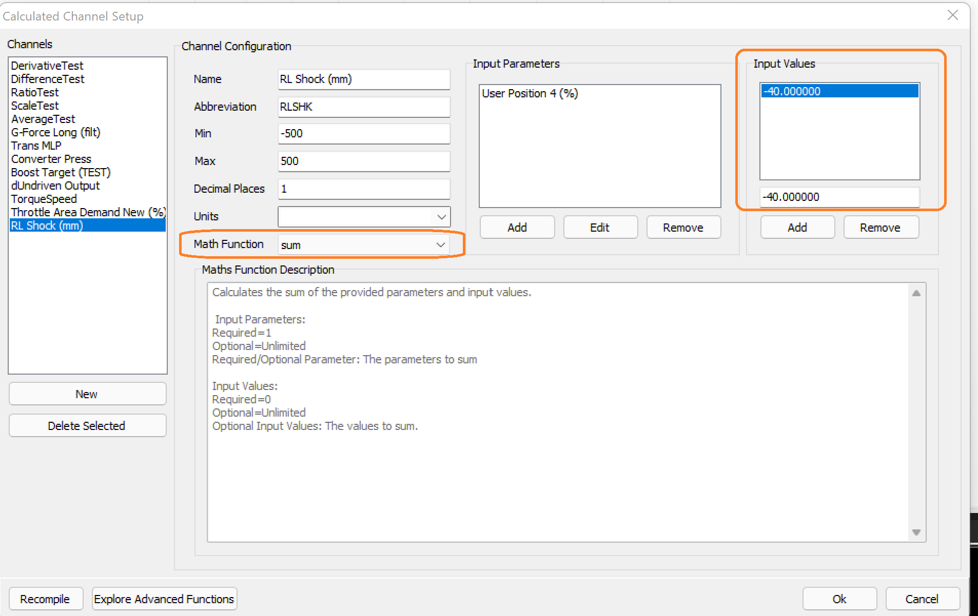
The calculated channel is created using the “sum” Math Function.
The Input variable of -40, zeros the value in the data logger/live parameters.
The value needed can be derived easily by looking at the current User Position channel, and then quickly entered to adjust the value, without re-scaling the position input.