Idle Valve Area Table
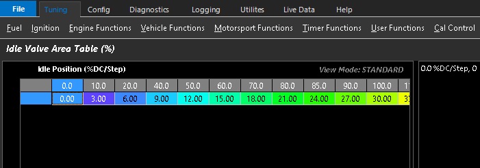
Idle Valve Area Table %
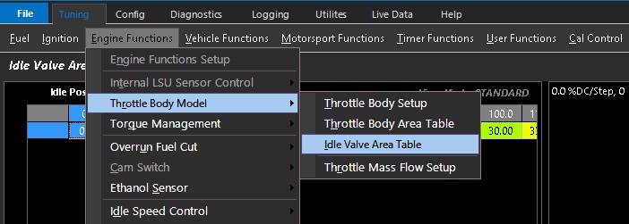
Tuning –> Engine Functions –> Throttle Body Model –> Idle Valve Area Table %
When Throttle Mass Flow is utilized without a DBW throttle - I.E: 3: ON x1 Cable Throttle Body
The area of the idle valve needs to be accounted for in the TMF calculation.
The Idle Valve Area Table % allows setting & adjustment of the correlation between Idle Valve Area and the Idle valve step position or duty cycle. These values then feed into the airmass calculation and add to the Throttle Area Demanded and Throttle Effective Area
The table is user generated & should be verified for accuracy.
Method 1 – MAF verification
If the application is using a calibrated MAF sensor. Then the idle valve area % can be adjusted and matched to TMF air mass VS MAF air mass at different idle air control valve step positions/duty cycle.
Method 2 – Matching Lambda
If no MAF sensor is available, setting fuel trims to 0 (or near 0), you can adjust the idle valve area to match the target mixture very quickly
(throttle area verification required prior to these steps)
** The only way to truly validate error in the TMF calculation is to use Method 1
** Some extreme applications where live Lambda is unstable may be more difficult to map with Method 2