Knock Control Setup
Tuning Knock Control
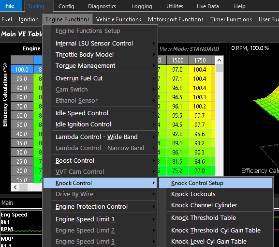
Tuning -> Engine Functions -> Knock Control -> Knock Control Setup
Knock Control Setup
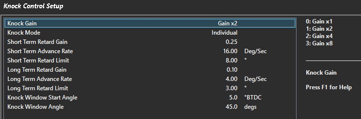
- Knock Gain - Gain added to knock signal (can multiply)
- Knock Mode - 0 = Global 1 = Individual (allows ECU to detect per cyl)
- Short Term Retard Gain - Retard for each percentage over the knock threshold
- Short Term Advance Rate - Rate at which timing is reintroduced when Short Term Retard is 0
- Short Term Retard Limit - Maximum Short Term Retard that can be applied
- Long Term Retard Gain - Long Term Retard applied based on Short Term Retard
- Long Term Advance Rate - Rate at which timing is reintroduced to Long Term Trim when Short Term Retard is 0
- Long Term Retard Limit - Maximum Long Term Retard that can be applied
- Knock Window Start Angle - Point at which ECU will start to sample the Knock Signal
- Knock Window Angle - The length in degrees in which the ECU will sample the Knock Signal
** Knock Window Angle must be less than the angle between TDCs
<90 degrees V8
<60 degrees V12
Knock Lockouts
- RPM Lo Lockout - Knock Control will be OFF below this RPM
- RPM Hi Lockout - Knock Control will be OFF above this RPM
- Post Start Delay - Delay in which Closed Loop Knock detection is active
- TP Lockout - Minimum Throttle Position before Knock detection is active
- dTP Lockout - Maximum Throttle Rate of Change in which Knock detection can become active
- dMAP Lockout - Maximum Manifold Pressure Rate of Change in which Knock detection can become active
- User Lockout - Allows user to create custom lockout channel
Knock Channel Cylinder
Select the appropriate Knock Channel (Knock Sensor) for each cylinder
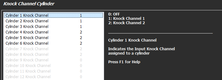
Example - 6 cylinder with two knock inputs
Knock Threshold Table
Table in which the maximum allowable measured Knock Level is allowed
Knock Threshold Cyl Gain Table
Used to multiply the signal gain per cylinder
** The X-Axis MUST be set to the Cylinder Numbers
Knock Level Cyl Gain Table
Used to multiple the knock level per cylinder
** The X-Axis MUST be set to the Cylinder Numbers