Cal Control
Cal Slot Control
This function in an extremely powerful feature which allow the user to customize special calibration slots.
There are 4 calibration slots available.
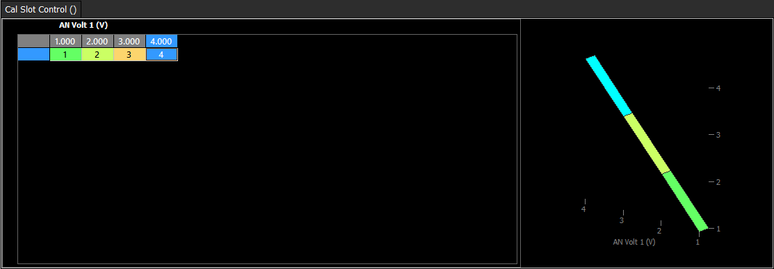
There are 4 Calibration slots which the user may configure. The cal slot is controlled through the 3D user table “Cal Slot Control”. Below is a simple example of how the cal slots could be switched. In this case AN Volt1 has been configured on the X axis. If AN Volt 1 is between 0.0V and 1.49V then Cal Slot 1 will be selected. If AN Volt 1 is between 1.50V and 2.49V then Cal Slot 2 will be selected and so on.
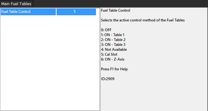
The corresponding table must be configured to be Cal Slot controlled. In this case the Fuel Tables will be configured to be controlled by the Cal Slot.
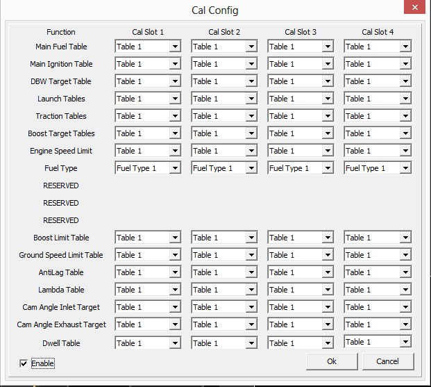
Below is the Cal Config table. This is where the tables are linked to the Cal Slot. In the below example Table 1 is used no matter what Cal Slot is selected.
The slot positon is defined by the setup of the Cal Slot Control table.
The Cal Slot Control table can be expanded into a 3D axis and any runtimes can be used to select each slot. This can be setup to use simple digital switch inputs, rotary position sensors, and/or any other runtime the user needs. This includes live runtime data that can aid in “automatic” cal switching.
Examples table axis:
Simple digital input
Rotary position switch
Analog voltage input
Temperature runtimes
Dual tune enable runtimes
Engine load runtimes
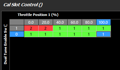
The above example looks at Dual Tune Enable switch as a condition for the Y axis, but the slot position is still dependant on Throttle Position on the X axis. If the engine is throttled past 20%, the ECU will automatically switch back to Cal Slot 1.
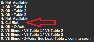
***In order for the Cal Slot configuration to work properly, under all Table Controls (see Table Control) being used, “Cal Slot” must be selected***