Pedal Position Demand Filter
Introduction
The ECU takes the raw Pedal Position Sensor 1 input, passes it through exponential filter to help smooth out signal fluctuations, then generates a new runtime Pedal Position Demand.
| Pedal Position Sensor -> EXPONTENTIAL FILTER -> Pedal Position Demand |
|---|
The filter coefficients for the exponential filter are adjustable using a table. These filter coefficients can be used to heavily filter small throttle corrections, while allowing large throttle changes to have little or no filtering. By heavily filtering small throttle corrections, throttle sensitivity can be reduced, helping the throttle “feel” when driving over bumpy roads or when making small throttle changes. Little filtering when making large throttle changes helps to give a fast throttle response when a large acceleration or deceleration is requested.
See the DBW Torque Management help topic for more information on the process of converting Pedal Position to Throttle Area to DBW Servo target.
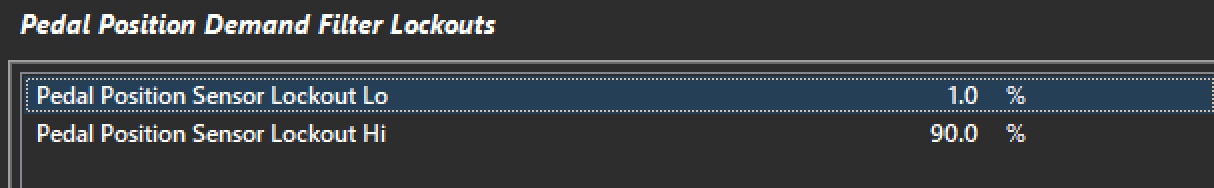
Pedal Position Demand Filter Lockouts
These settings allow for the lockout of the pedal filter based on the pedal position.
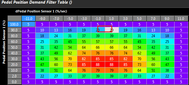
Pedal Position Demand Filter Table
This controls how much filtering is applied. It is common to filter heavily at low rates of pedal position sensor output in order to achieve a smooth driver torque demand.
0 = Filtering OFF
99 = Max Filtering
Important Note: It is strongly recommended to span the table axis as follows:
- X - Axis = Rate of Pedal Position sensor change
- Y - Axis = Pedal Position Sensor
Example
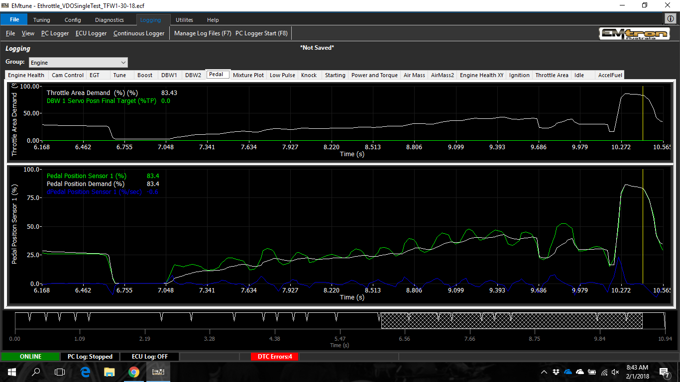
Using dPedal Position Sensor 1 and Pedal Position Sensor 1, the Throttle Area Demand can be softened at low dPedal rates whilst also giving the ability to change the filtering based on the raw pedal position.
Reviewing PC/ECU logs will allow the user to achieve the desired effect.
- Top Plot (white trace) shows Throttle Area Demand
- Bottom Plot shows the Pedal Position Sensor (green trace) vs Pedal Position Demand (white trace)