Pedal to Throttle Area Demand Translation
Introduction
As discussed at the beginning of this section DBW Torque Management the ECUs Torque Management using DBW requires the plate control to be in Throttle Area, not Throttle position.
.
Pedal to Throttle Area Demand Translation Tables
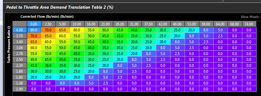
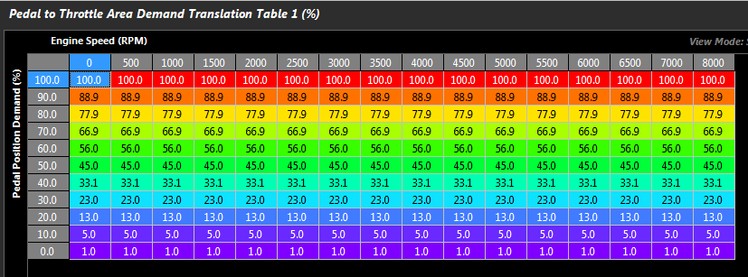
Pedal to Throttle Area Demand translation is performed using a 3D table. Three tables are available, only 1 can be active at any one time.
NOTE: This table targets Throttle Area (NOT DBW Servo Position)
The relationship of Servo Position should be ignored with a properly tuned Throttle Body Area system in the Throttle Body Model. Torque targeting should be the overall mentality of this map, and while with everything configure as it should (TMF, etc), linearized table may produce linearized Driver Demand, this may not be ideal for how the vehicle will want to drive. More often than not the demand table will end up in a shape where the higher end of the table (60+) has much larger values in it - to demand more torque.
The Y-Axis runtime should be spanned using “Pedal Position Demand” which is a filtered version of the raw Pedal Position sensor. See Pedal Position Demand Filter .
A typical runtime for the X-Axis is Engine Speed.
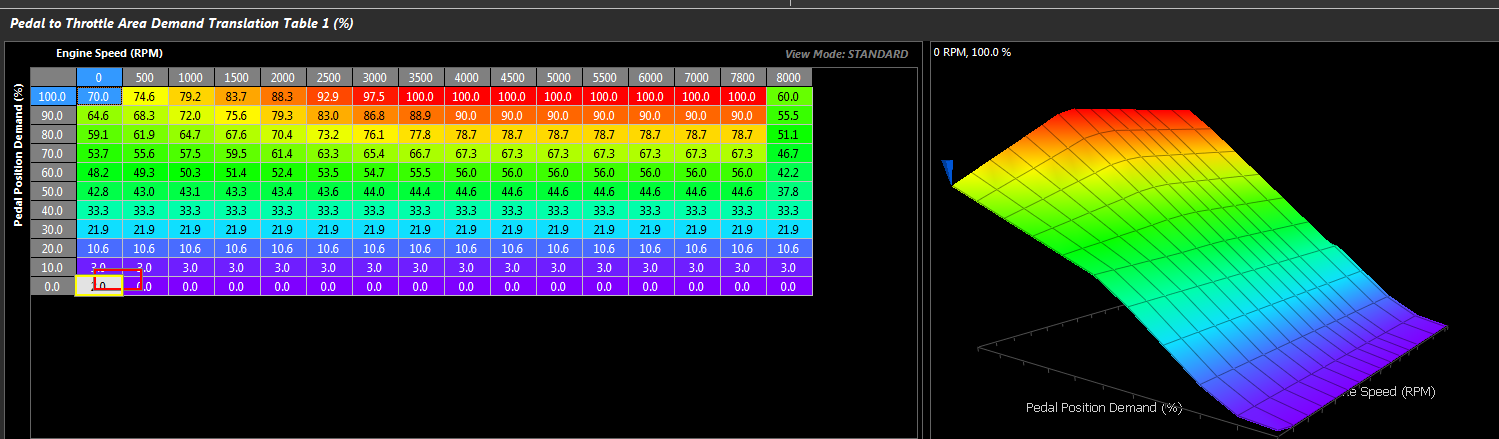
Pedal to Throttle Area Demand Translation table
Pedal to Throttle Demand Translation Clamp Table
This is a 3D table that clamps the maximum allowable throttle area. If no clamping of the Throttle Demand is needed, a single value of 100% can be used.
Two examples are shown below.
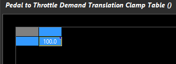
Basic Throttle Area clamp table (no Throttle Demand Clamping is needed)
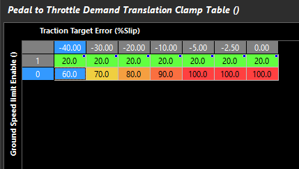
Advanced clamp table (based on Traction Target Error and Ground Speed Limiter)
Pedal to Throttle Area Demand Translation Table Control
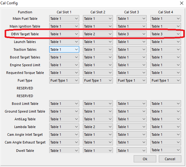
As mentioned at the start, there are 3 tables which can be control in a variety of ways. The following options are available
0: N/A (Tables OFF)
1: ON – Table 1 (Table 1 Available)
2: ON – Table 2 (Table 2 Available)
3: ON – Table 3 (Table 3 Available)
4: N/A
5: Cal Slot (Cal Slot Control selects active table)
6: ON – Z-Axis (Z Axis Table selects/blends active table)
7: ON – Table 1 = DBW 1/Table 2 = DBW2 Air Bleed
Modes 1-3: Activate individual tables
** Mode 1 is most common (Table 1 activated)
Mode 5: Allows Cal Slot Control to select the active table (See Cal Slot Control)
Mode 6: Enables a Z-Axis table that allows selection/blending of the active table,
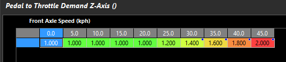
Axis based on Front Axle Speed. Units are active table
Mode 7: Allows two different drive by wire servos to have different targets. DBW Servo 1 controlling the main airflow into the engine, and DBW Servo 2 being used for a different purpose like DBW Air Bleed on turbocharged or supercharged engines.
Example
Pedal to Throttle Demand Translation Table 1 = DBW 1 Control .
Pedal to Throttle Demand Translation Table 2 = DBW 2. This is used for compressor surge control by venting excess air the engine cannot use.
This is a good example of how Emtron allows you to layer multiple functions together to obtain a desired result