Sensor Installation and Wiring
Sensor Installation
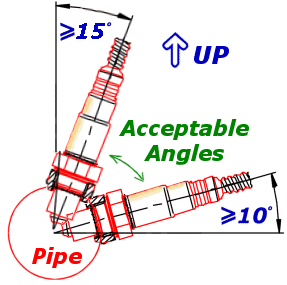
Installation angle must be inclined at least 10° towards horizontal, (electrical connection upwards) up to a maximum of 75°. This prevents the collection of liquids between sensor housing and sensor element during the cold start phase.
The angle against the exhaust gas stream should be aimed as 90°. Maximum inclination should be 90°+15° (protection tube towards gas stream) or 90°-30°.
NOTE: NEVER mount the sensor directly on the horizontal or within 10 degrees of the horizontal. Doing so will result in intermittent sensor shutdown.
Also route the sensor cable to avoid high moisture locations – just a small amount of moisture is enough to provide a conductive path within the connector that will upset measurement from the sensor.
Winter and salted roads compound this issue. Always check for a cracked or broken connector when strange results occur.
Noise Immunity
To minimize signal contamination and maximize noise immunity, the wire pairs shown in the below Table must be twisted. It is recommended to twist the wire pairs at a minimum one twist per 40mm of cable. This is very important and should always be implemented on the LSU sensor wiring.
| Pair 1 | Pair 2 | |
|---|---|---|
| Pump Current | <——-> | Cal Resistor |
| Nernst Cell Voltage | <——-> | Virtual Ground |
Wire pairing for twisting
NOTE: To avoid signal errors and loss of accuracy, a cable of a maximum length of 1.5 m between sensor and ECU is recommended.