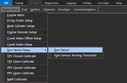
Sync Sensor
Sync Sensor
Sync Sensor Type
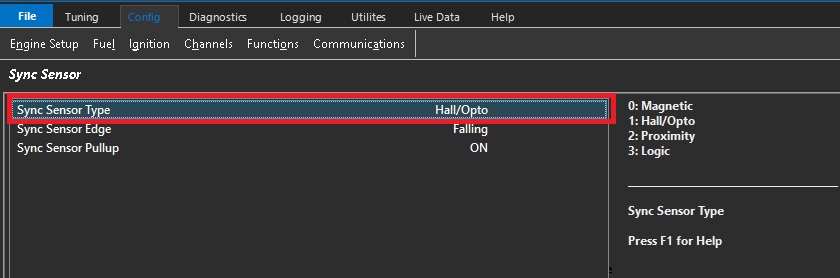
Inputting a numerical value from 0 to 2 enables setting of the sync sensor type.
0: Magnetic
1: Hall/Opto
2: Proximity
3: Logic (Available in future)
Magnetic sensors are voltage generators. They produce voltage, so they will produce a sign wave signal, and generally produce higher voltages as the tone ring speed (engine speed) increases. They can be identified easily by usually having TWO WIRES only. Almost all of them will have a third wire, but this is almost always a shield wire, which must be connected to the ECU shield pin.
Wiring for Magnetic sensors is particularly sensitive, as since they can produce low voltages (especially at lower engine speeds), they can be more susceptible to interference issues. Proper wiring practices must be adhered to without fail especially with magnetic sensors. Always use the dedicated trigger input pins on the ECU (Crank +/- Sync +/-), with correct sensor polarity.
** Polarity of Magnetic sensors must be correct. See Uses of Scope - Improper Crank/Sync Sensor Polarity
Hall Effect sensors produce square wave signals. They require a voltage source (Emtron has a dedicated 8V voltage source pin for CAS), and can be identified generally by usually having THREE WIRES. Supply, signal, and ground.
Always use the dedicated trigger input pins on the ECU (Crank +/- Sync +/-)
** Do not connect Hall Effect (or any other “Pulsed” sensor grounds) to Analog Volt Ground pins
Sync Sensor Edge
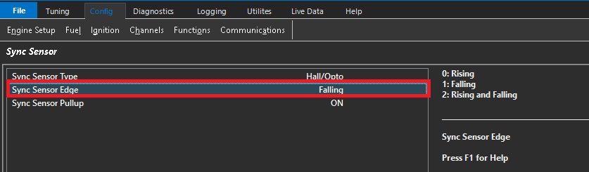
Inputting a numerical value from 0 to 2 enables setting of the sync sensor edge type.
0: Rising
1: Falling
2: Rising and Falling
Edge configuration should only be adjusted when using non Pre-Defined Engine Decoding Modes
** When Selecting ANY Pre-Defined Engine Decoding mode (3 +), Crank/Sync Sensor type, Edge configuration, Pull up configuration is all pre-configured for the user. The user should not need to adjust these.
In general as stated under Crank Index Sensor, falling edge would be the “fast” edge for sensor signals, but sync sensors are not generally used for “timing” of the engine, and more for synchronization of engine cycles. Therefore, edge configuration has more options.
For example, rising OR falling edge options could be deemed best depending on where the sync tooth position is in relation to the Crank “Index Tooth”. In some cases, if the Sync Edge is too close to the Index Tooth edge, there could be issues with identifying the engine stroke, especially at different engine speeds if there any chance of mechanical wandering of the sync trigger (IE - fixed crank trigger and belt driven cam trigger). Using the Scope can identify these issues, and potentially changing the sync sensor edge can correct theses issues
** Note - Sync Lockout is also an option with an unreliable Sync Signal (only to be used with Missing Tooth Crank Trigger)
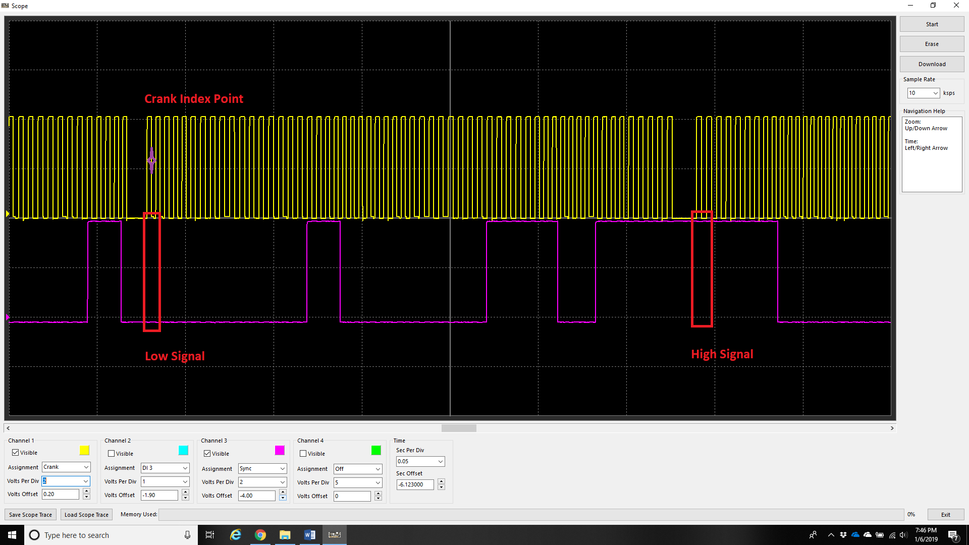
Rising and Falling
Engines with multi-tooth sync sensors usually will have a “long” tooth during the “crank index point”. Normally, a custom decoding mode is needed to run the engine with multiple sync teeth, but in this case because there is a clear difference in signal on the sync input on each stroke (low vs high), the ECU can determine the stroke immediately (this is the fastest way to decode starting/720 sync). Set Sync Sensor Edge configuration to Rising and Falling for these trigger types.
Sync Sensor Pullup
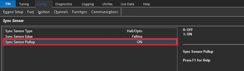
The numerical disable/enable input to control the 5volt pull-up available for Hall Effect, Optical & Proximity Sync sensors.
0: OFF
1: ON