Throttle Body Setup
Introduction
The Throttle Body setup consists of 2 main parts:
- Throttle body diameter and scaler.
- Throttle body area table.
Settings are adjusted from the Engine Functions -> Throttle Body Model menu. Throttle body templates are also available to load into the ECU from the File -> Import Module File menu
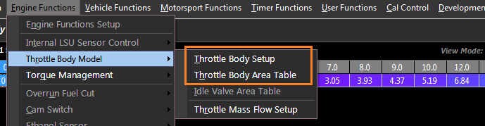
See the DBW Torque Management help topic for more information on the process of converting Pedal Position to Throttle Area to DBW Servo target.
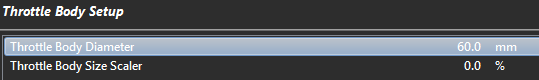
Throttle Body Setup
The Throttle Body diameter and scaler can be adjusted from this menu.
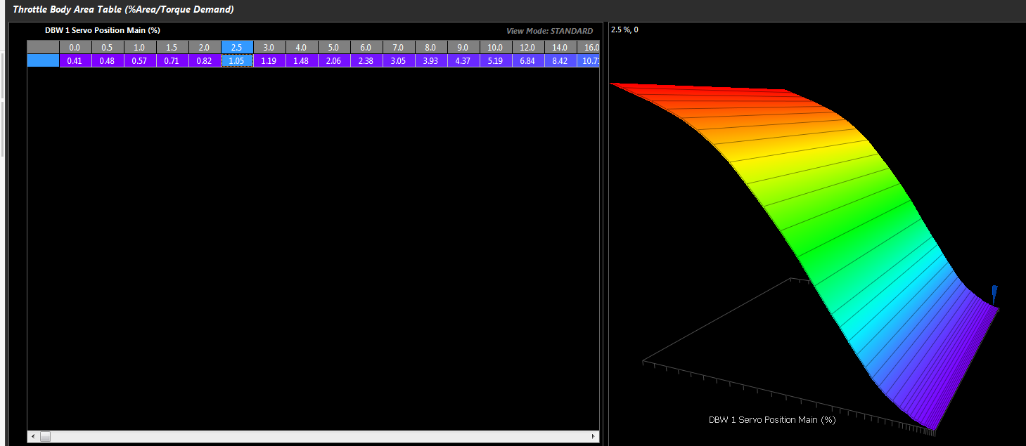
Throttle Body Area Table
The Throttle Body Area table is a 40 cell correlation table; it gives the direct relationship between Throttle Area and Throttle Position (Servo Position). The ECU uses this table to convert any Throttle Area request into Servo Position which is then used as the DBW Target. Throttle Body templates are available to load into the ECU from the File -> Import Module File menu.
Example:
Throttle Area Demand from the pedal = 4.37%
Using the table in the below image, the ECU would find the 4.37% area and correlate this to 9.0% Servo Position. The DBW Servo Position Target therefore becomes 9.0%
i.e the ECU is asking for 4.37% area and moves the throttle plate to 9.0% servo position to achieve this.
Nissan GT-R R35 Throttle Body Area table